
Cooling storage units
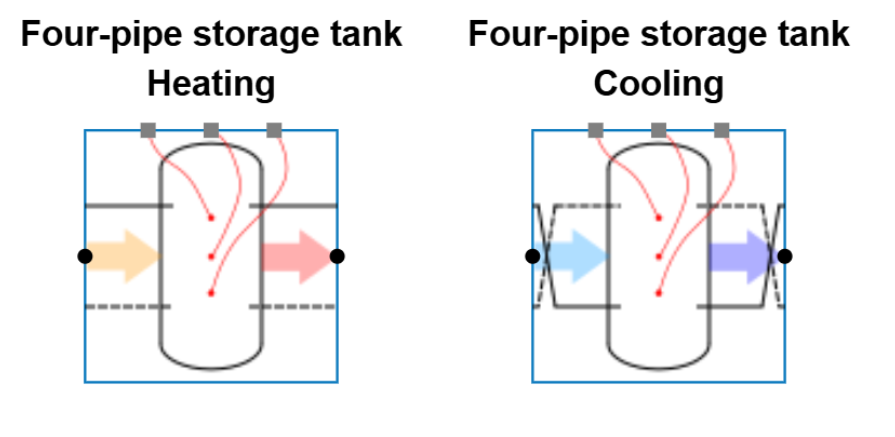
Thermal storage tanks for cooling are very similar to thermal storage tanks for heating (Thermal storage heating )
However, a key difference for cooling storage tanks compared to heating is the connection orientation. By default, the supply is connected at the bottom of the tank for cooling. Correspondingly, the return is connected at the top of the tank. This arrangement is clearly visible in the base circuit visuals and reflects the typical connection approach in standard cooling applications.
Direct and indirect
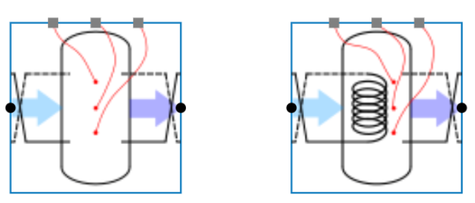
The central cooling storage units can be divided into two types: Direct and indirect
-
Direct units do not include a coil functioning as a heat exchanger. The primary and secondary sides are directly connected through the same water volume.
-
Indirect units contain a coil that separates the primary side from the secondary side. This hydraulic separation is in most cases required when glycol is present on one side but not on the other.
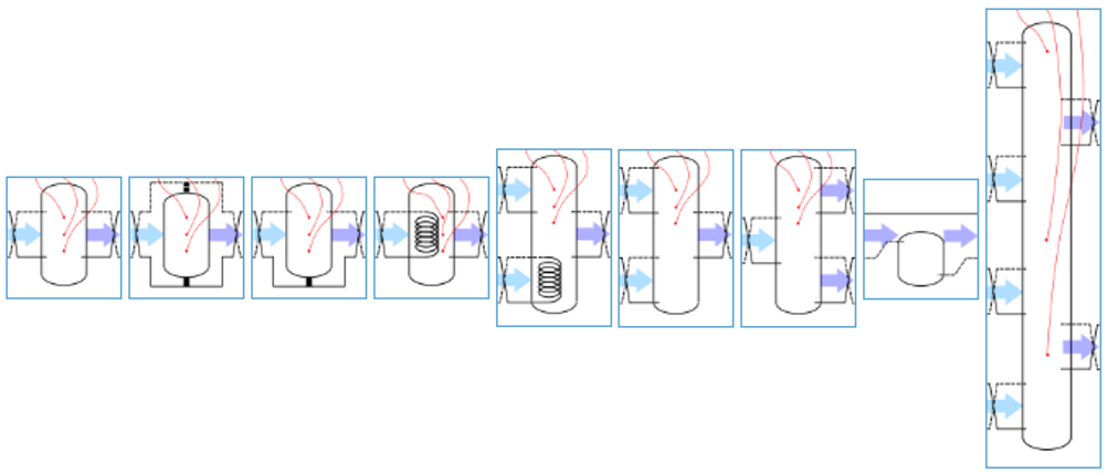
Besides the base circuits (BCs) shown above, more BCs are available combining different types or allowing multiple connection possibilities.
Two-pipe and three-pipe storage tanks
In addition to thermal storage tanks with four (or more) pipe connections, the Hysopt library also includes two buffer vessels (BCs) with respectively three and two pipe connections (see figure below). All variants in Hysopt provide hydraulic separation, which is why the two- and three-pipe tanks feature wide connections at both the top and bottom.
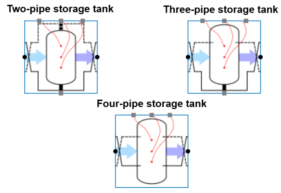
Depending on the designer’s preferences and the application, two- or three-pipe storage tanks can offer certain advantages. For example, these configurations allow supply water from the primary side to be delivered directly to the secondary side without passing through the tank. This is particularly useful during start-up, ensuring the secondary side immediately receives sufficiently low supply temperatures without needing to pre-charge the buffer.
The three-pipe variant includes a direct connection at the bottom for supply, while the top features two connections. This ensures that the return water from the secondary side passes through the buffer before returning to the production units, which helps to mitigate highly fluctuating return temperature swings into more stable conditions towards the primary side.
Thermal storage for cooling (all variants)
Design parameters
The following parameters are relevant for the design:
Design heat flow and temperature regime
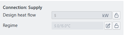
Both parameters can be set and locked by the user. If they remain unlocked, Optimise system components will propagate the cooling demand and temperatures from the secondary side through the storage tank to the primary side.
For thermal storage Base Circuits with more than one primary and/or secondary side connections, the design heat flow and temperature regime must be input manually.
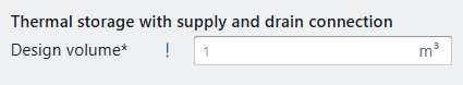
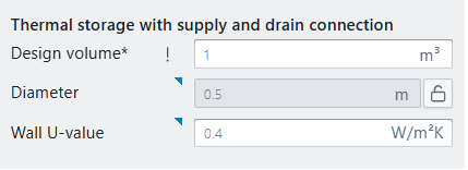
Design volume: the design volume of the cooling buffer must be entered manually by the user. TO optimise the tank volume to a specific production unit, we advise to perform sensitivity analysis on the tank volume.
Presusre drop in design/Kv value (for indirect units): when the storage unit includes a coil, the Kv value or pressure drop in design should be entered by the user to correctly calculate the pump head on the primary side.
Simulation parameters
For simulation, the following parameters are relevant:
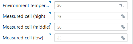
Environment temperature as reference temperature for the surroundings to simulate the thermal losses of the cooling buffer. Measurement cell positions specified in percentages of the total height, to indicate sensor positions for control.
U-value and diameter of the tank will define the heat losses during simulation. The U-value refers to the insulation performance, whereas the geometry of the buffer tank will determine the heat loss surface area. The buffer tank geometry is automatically scaled with the design volume, if unlocked.
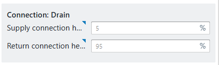
Connection heights: supply and return heights can be freely positioned. By default, supply is at 0% (bottom) and return at 100% (top), but intermediate connections (e.g. at 50%) can be modeled as well.
Indirect cooling storage tanks with a coil also require the UA value to simulate thermal power transfer from the primary side into the storage.