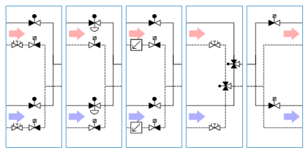
The change-over systems library gathers circuits that can be connected with the header/collector or end-units to control the net thermal power leaving the technical room or the power going towards a separate change-over system.
In general, these units are split into two categories:
-
Mergers
-
Change-over merger with modulating 2-way valves
-
Change-over merger with pressure independent control valves
-
Change-over merger with modulating 2-way valves and flow regulators
-
Change-over merger with 6-way valves
-
-
Splitters
-
Change-over splitter
-
Control of change-over systems
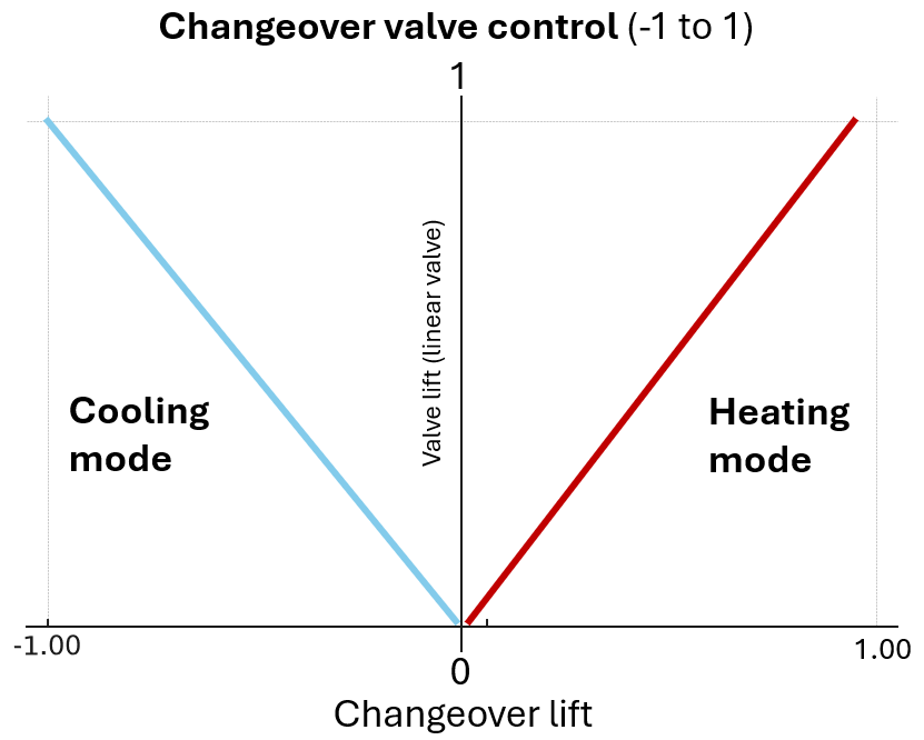
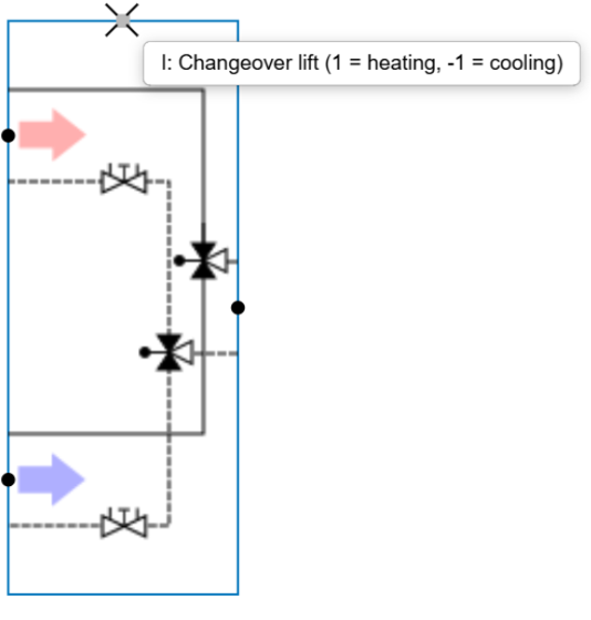
In Hysopt, valve position control for changeover valves happens through the Changeover lift connector node (see figure below). The control of the valve position of changeover systems differs from single-application valves (used only for heating or only for cooling).
-
For single-application valves, the position ranges from 0 to 1, where 0 = closed and 1 = fully open.
-
For changeover valves, the valid range in Hysopt is -1 to 1:
-
-1 to 0: Cooling valve opens while the heating valve remains closed.
-
0 to 1: Heating valve opens while the cooling valve remains closed.
-
This approach reflects practical situations where a single analog control signal (typically 2–10 V) is split into separate ranges for cooling (e.g., 2–4.5 V) and heating (e.g., 5.5–10 V). In Hysopt, this split-range signal is normalized to the -1 to 1 scale. Note that no dead band between the lowest heating mode voltage and highest cooling mode voltage is present in Hysopt, whereas recommended in practical systems.