Designing and optimizing HVAC systems requires the ability 'to play with the design parameters. The Hysopt software includes powerful tools to access and change the systems' design parameters in a fast and synoptic way.
Parameter box
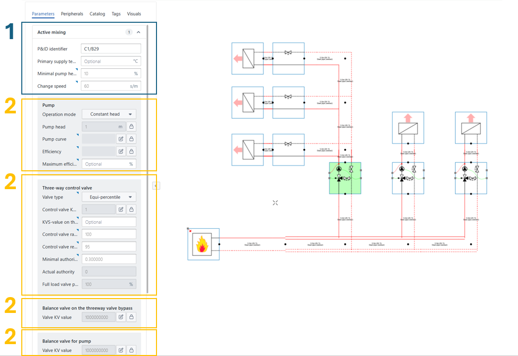
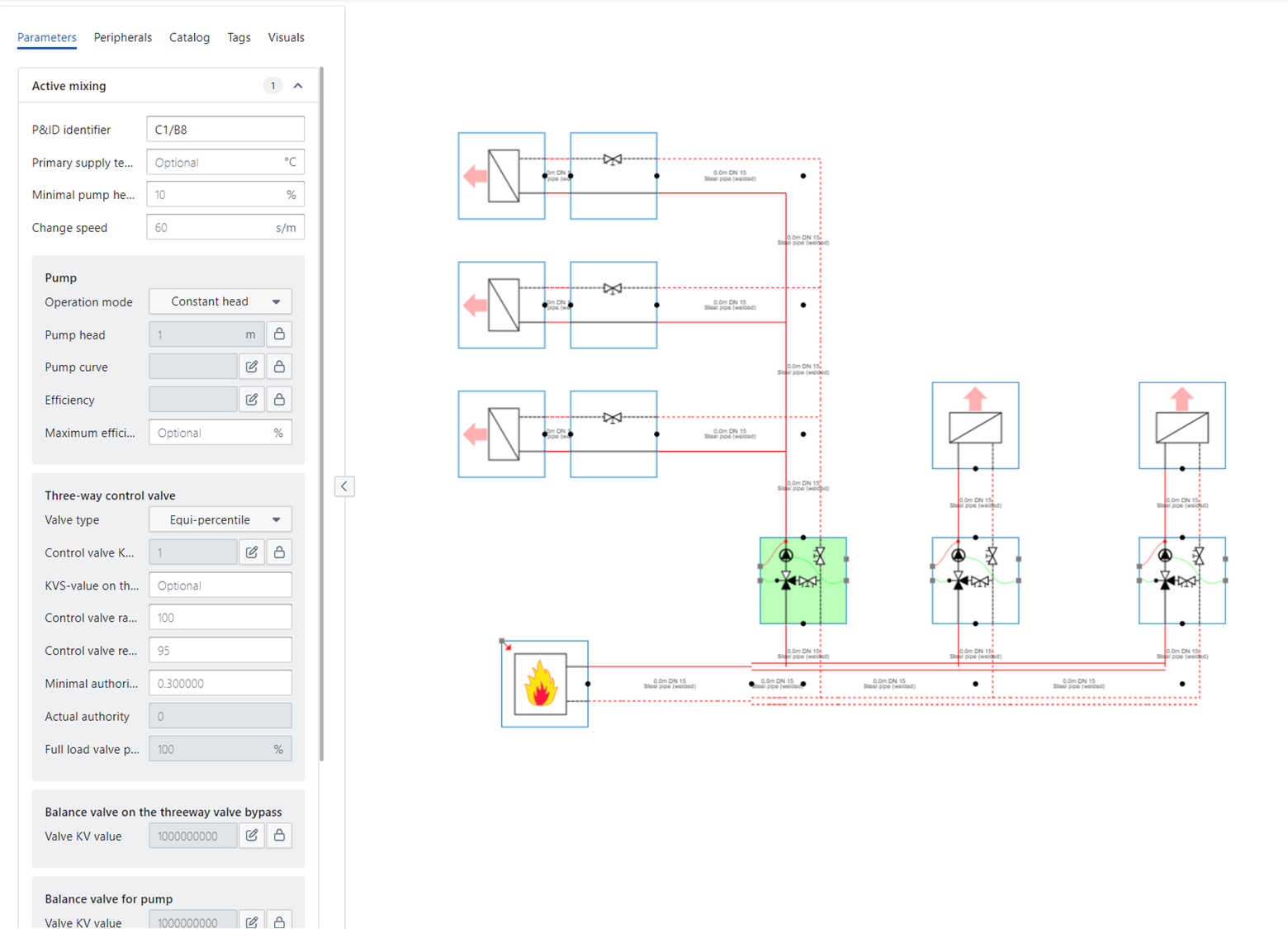
When left-clicking on a base circuit, a parameter box appears on the left side of the canvas in which the parameters of the respective base circuit can be modified. For base circuits containing multiple hydraulic component, the parameters are arranged according to the respective components and grouped in a grey box. If not all parameters are shown (in case of a large number of parameters) you can scroll down in the parameter box using the mouse wheel.
The selected base circuit is marked green on the drawing canvas.
The blue box highlighted with “1” in the figure below comprises all parameters of the selected base circuit that are not part of a single component.
The yellow boxes highlighed with “2” are all separate components that are part of the base circuits, having all the corresponding parameters to that component grouped in the grey box.
Advanced parameters 
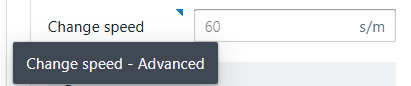
To enhance user guidance, parameters that are complex but less critical are designated as “Advanced parameters,” indicated by a blue triangle ![]()
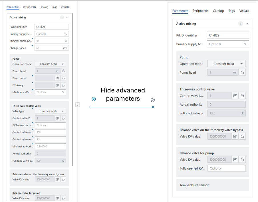
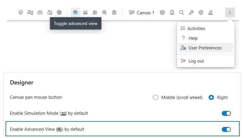
For a more streamlined interface, users can opt to hide Advanced parameters using the “Advanced View Toggle” in the upper-right corner, switching to a simplified view focused on essential settings. The example below shows that the active mixing circuit is less complex to use with the Advanced parameters hidden.
Since some users prefer having advanced parameters visible at all times while others prioritize key parameters, users can adjust the default “Advanced” toggle mode when launching the software. Hysopt recommends the following default settings based on user type:
-
Early Hysopt Users, Conceptual Designers: Deactivate Advanced view by default.
-
HVAC Experts, Detailed Designers: Activate Advanced view by default.
Parameter Types in Hysopt
Hysopt distinguishes between three types of parameters in the parameter list: input parameters, output parameters and lockable parameters. Below is an explanation of each type, using the example of the "Active mixing" configuration from the figure below:
Input Parameters
Input parameters are editable fields that require user input. They are displayed with a white background. Some examples of active mixing circuits are:
-
Primary supply temperature (optional input)
-
Minimal pump head
-
Change speed
-
Operation mode of the pump
…
Input parameters are necessary for defining system characteristics such as temperatures, pump settings, design heat flow, etc. at places where Hysopt cannot derive those values from other system characteristics.
You can easily recognise the minimal set of parameters that you are expected to fill in by being input parameters that are not marked “advanced” or “optional”.
Output Parameters
Output parameters are calculated parameters that cannot be edited by the user. They are displayed with a grey background.
Output parameters provide system-calculated values based on user input and the system configuration and are shown to the user for informative reasons.
Some examples of active mixing circuits are:
-
Actual authority
-
Full load valve position
Output parameters are only updated after calculation steps. They are never updated real-time when an input parameter has just been changed. Therefore, ensure that you systematically execute the relevant calculation steps (typically optimise system components) before drawing conclusions regarding output values.
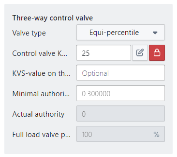
Lockable Parameters
Lockable parameters can be recognised by the padlock icon 
When unlocked (grey): The parameter behaves as an output, meaning it is calculated by the system.
When locked (white): The parameter becomes editable, allowing the user to provide a specific value.
Lockable parameters are especially useful in renovation projects where certain design parameters are fixed, or when the user prefers to overwrite specific calculated values.
Some examples in the active mixing circuit:
-
Pump head in pump
-
Pump curve in pump
-
efficiency curve in pump
-
Control valve Kvs
How to use lockable parameters?
The Hysopt software calculates the optimal system parameters. However, as a designer, you are always able to change parameters as you like. By clicking on the lock icon a parameter, or just filling in a value, the lock-icon will be activated and forces the user-defined value in the calculations (the lock icon is marked in red). This way the software sees this parameter as a hard input value instead of an (optimized) calculation result. This feature is particularly useful in renovation projects where the existing parts of the system must be modeled 'as is' by locking the parameter values.
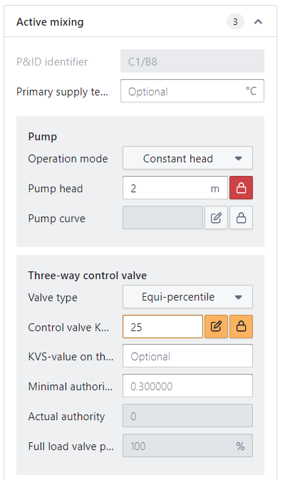
Note that when several base circuits are selected (see 'Changing parameters for multiple base circuits'), the lock icons can be marked grey, red, or orange:
-
A grey marked lock icon means that the parameter value is unlocked
-
A red marked lock icon indicates that the parameter value is locked for all base circuits within the selection
-
An orange marked lock icon means that the parameter value is locked for some of the base circuits within the selection
Changing parameters for multiple base circuits
In order to easily modify system parameters in large systems (e.g. for sensitivity analysis), parameter values can be changed for multiple components at once:
-
using 'Alt+Click' within one canva
-
using 'Shift+Alt+Click' to span multiple canvasses
-
using a drag selection
Using 'Alt+Click' within one canvas
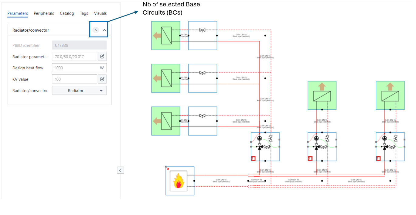
When pressing the 'Alt' button while clicking on a base circuit (or pipe), all base circuits of the same type will be selected at once. The number of selected base circuits is shown at the top of the parameter box. Uniform parameters (parameter values are the same for all base circuits in the selection) are marked in black whereas a red marked parameter value indicates that different parameter values are applied within the selection. When overwriting a red parameter value, the new parameter value will be marked in black which means that it is now a uniform parameter value.
In the example shown below, all radiators are selected at once by using the 'Alt-Click' selection. The total number of selected radiators (5) is shown at the top of the parameter box. The temperature regime 70/50/20°C and the Kv-value are marked in black as the same values apply for all five radiators. The design heat flow is marked red as the selected radiators have different values for this parameter.
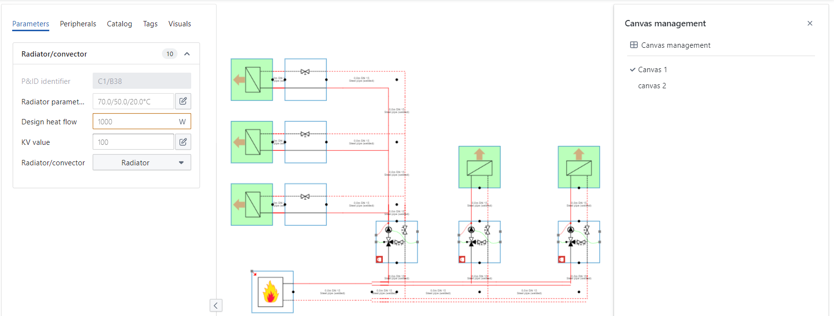
Using 'Shift+Alt+Click' to span multiple canvasses
The 'Shift+Alt+Click' selection is the same as the 'Alt+Click' selection however it spans multiple canvasses (see 'Canvas Management') whereas the 'Alt+Click' selection is restricted to the canvas which is currently shown.
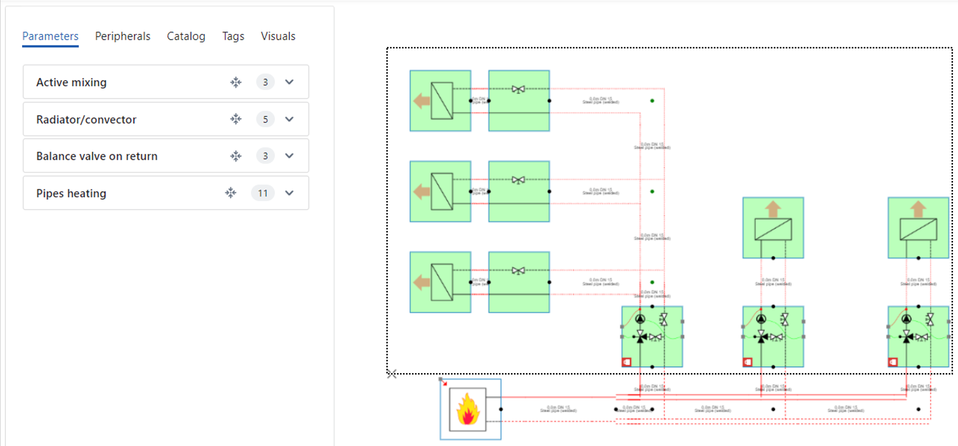
Making a drag selection
A drag selection can be made by dragging the mouse cursor over the desired area in the drawing canvas while holding the left mouse button. During the drag selection movement, a dashed line rectangle indicates the selected area. After the selection, the selected base circuits are marked green and the respective base circuits are listed in the parameter box. The respective parameter value appears when clicking on the name of the base circuit. You can also use the “select elements” ![]()
Input View (Progress tracking)
The Input View is a dedicated view mode designed to support users in completing the full parameterisation of their model before going into design calculations or a simulation. It can be activated via the Input View button in the top ribbon bar. The appearance and behaviour of the Input View can be customised in the user preference settings.
An example of the Hysopt canvas with the input view activated can be seen below.
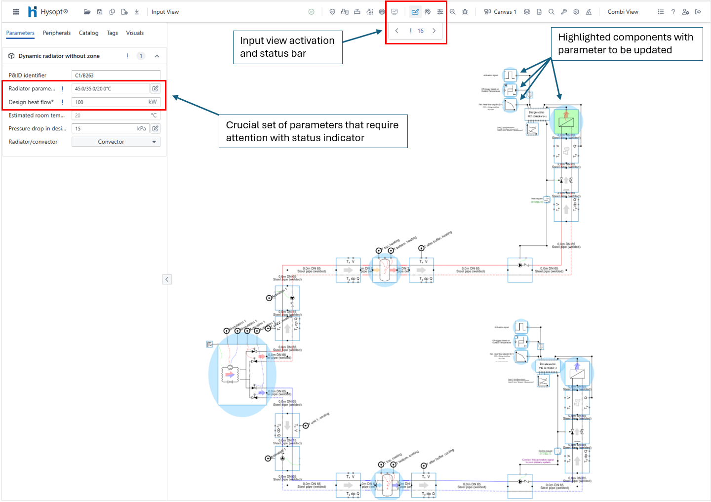
Required Parameters and Visual Feedback
With the Input View activated, Base Circuits (BCs) that contain parameters expecting a custom user input are highlighted. This minimal set of crucial parameters are called required parameters and are marked with an asterisk * in the parameter list. Hysopt uses this indication to guide users toward completing the crucial set of parameters in a model before a calculation or simulation is performed.
A warning is shown when a calculation or simulation is performed with relevant required parameters still non-validated. Note that required simulation parameters (e.g. Boiler setpoint, heating curves, …) will never trigger a warning in design calculations.
When a Base Circuit with unvalidated parameters is selected, you will see extra icons to the left of each required parameter field. These icons are the status indicators for that particular parameter, reflecting whether the parameter value has been manually confirmed or still requires validation. The icon updates automatically when the value is modified.
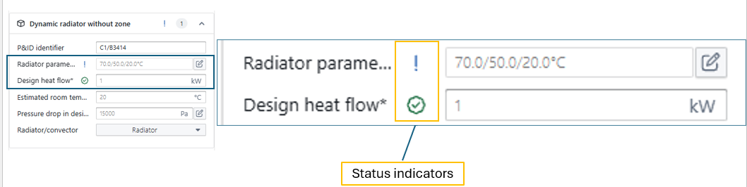
If you want to accept the default value of a required parameter, you can manually validate it by clicking the Status indicator. This confirms that the default value is applicable for your use case.
Input View is context-sensitive to your current model view (e.g., Simulator View, Calculator View, Combi View). The set of required parameters differs from focus-view so that applying the correct focus view will help you focussing on relevant parameters only.
Custom progress tracking
In addition to tracking required parameters, Input View also supports custom progress tracking at the Base Circuit level. Each Base Circuit has a status indicator that you can set freely to either TO DO or DONE, regardless of whether Hysopt considers any parameters required.
This allows you to highlight BCs as TO DO even if there are no required parameters (e.g., if you plan to input detailed design data later) or quickly mark many BCs as DONE once you've completed your review or input.
Customisation Options
You can customise how the Input View behaves and appears through the User Preferences. This allows you to tailor the experience to your workflow and visual preferences.
Two key settings are available:
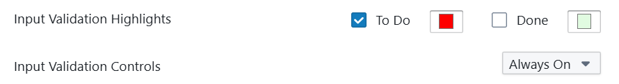
Input Validation Highlights
This setting allows you to choose the base circuit highlighting on the canvas with the input view activated.
You can:
-
Enable or disable the highlighting of each category using the checkbox.
-
Choose the colour of the highlighting for the non-validated (To Do) and Validated (Done) Base circuits
Input Validation Controls
This dropdown allows you to control when the validation status icons are shown:
-
When Input View is Active: Validation icons are only shown when Input View is explicitly activated.
-
Always On: Validation icons are shown at all times, even when the input view is not activated
Default/non-default (Change tracking)
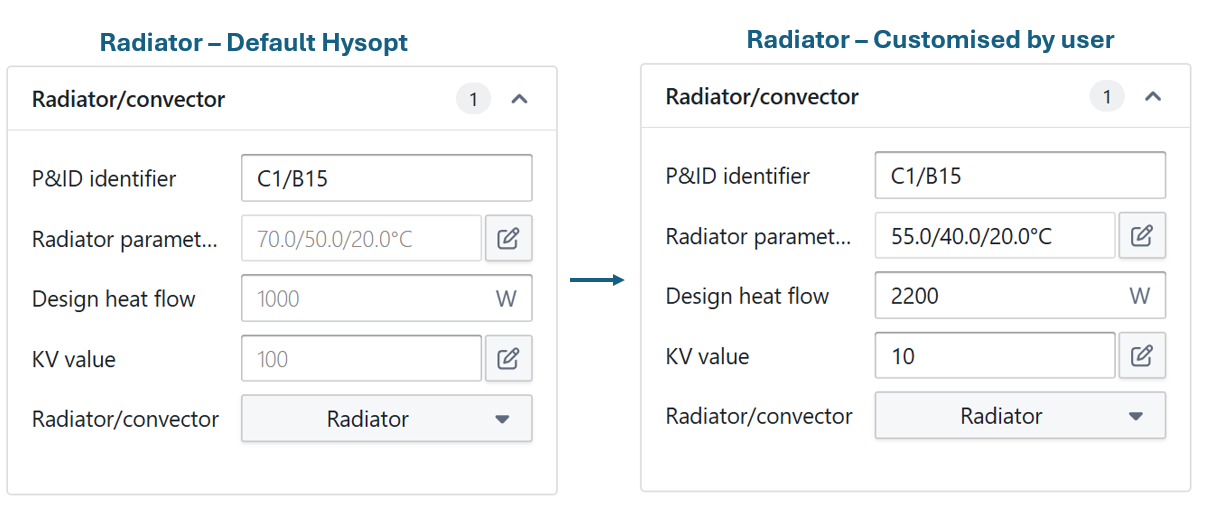
The Change Tracking functionality in Hysopt allows users to easily identify modified parameters at a glance. By default, parameters that retain their original (default) values appear in grey text, resembling a placeholder text. Once a parameter value is changed by the user, its font color switches to standard black, clearly distinguishing it from unmodified values.
This color-coding system helps users quickly assess which parameters have been customized throughout a project. By visually differentiating between default and modified values, users gain a clearer overview of their configuration changes, which can be especially useful for troubleshooting or refining a model over time.
Example of Change Tracking
The following example illustrates how Change Tracking works, showing the contrast between grey (default) and black (modified) font colors in the parameter fields.
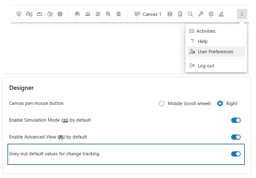
Default Settings for Change Tracking
Recognizing that some users may prefer a consistent black font for all parameters, regardless of modification status, Hysopt allows this functionality to be toggled on or off in the user preferences. To disable Change Tracking, users can adjust this option in the user setting menu, ensuring all parameters remain in standard black font.