
Heat exchangers are common parts of hydronic systems. They transfer heat from one system to the other whilst hydraulically separating them.
Heat exchanger types
At the moment, the Optimiser supports two heat exchanger BC types:
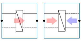
Heat exchanger for heating
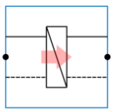
This BC is used when the main function of the HX is to transfer heat from a primary side towards the secondary side. Generally, a heat source is situated further upstream the primary gate, while a group of end units is situated further downstream the secondary gate. The heat demand, design flow rates and temperature regimes will be propagated in the model from the secondary to the primary gate during the ‘compute design flows’ step.
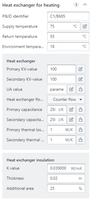
The BC itself has three parameters, which determine the primary temperature regime:
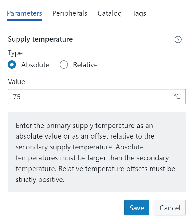
Supply temperature: The primary flow design temperature further upstream the primary gate. By clicking on the pencil icon, the user has two options for determining the design flow temperature:
-
Absolute temperature: The user fills in the design temperature manually. Keep in mind that this value must be larger than the secondary design temperature.
-
Relative temperature: The user creates an offset to the secondary design temperature. Keep in mind that the offset must be strictly positive.
Return temperature: This is an optional parameter and must only be filled in whenever the UA-value of the HX is unknown. By filling in a return temperature, the Optimiser will calculate the HX’s UA-value using the available information on the propagated design capacity, temperature regime and design flow rate at the secondary gate. By default, this parameter is set to 55 °C
By filling in the return temperature, the user directly imposes the temperature regime and the design flow rate that will be propagated further upstream the primary gate.
Environment temperature: The temperature of the room/environment in which the heat exchanger is placed. This parameter is used to take heat losses from the HX to its environment into account during simulation and is set to 18 °C by default.
The BC encompasses two components, which contain the actual model equations:
-
The heat exchanger
-
The heat exchanger insulation
Heat exchanger
The heat exchanger component has the following parameters:
Primary Pressure drop in design (or KV-value): A parameter for the pressure drop at the primary side of the HX.
Important: Don’t forget to save the calculated KV value. If you click somewhere else in the model before saving, the calculation will be canceled.
Secondary KV-value: A similar parameter as the ‘Primary KV-value’, but now for the secondary side of the heat exchanger.
UA-value: The UA value is a number that describes the heat exchanger’s effectiveness, dependent on the heat exchanger material type, size and used temperatures. It is the product of the heat exchanging area and the thermal transmittance. The thermal transmittance [W/m²K] or simply the U-value is the exchanged heat divided by the temperature difference over the heat exchanger per m².
There are some different possibilities to set this value correctly:
-
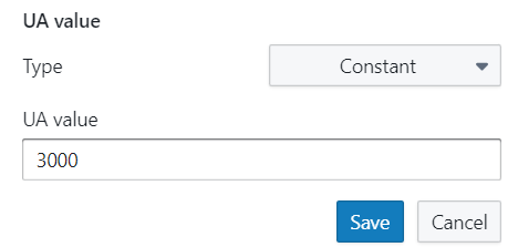
Constant: Used when a constant UA-value is known.
-
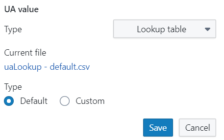
Look-up table: When UA-values are known for different flow rates, they can be filled in manually through a custom csv table. Check the default csv table to ensure that your table is filled in similarly to make it compatible with the Optimiser.
-
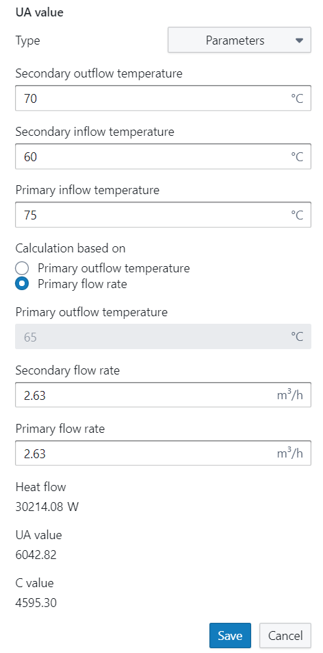
Parameters: When the UA-value is not known, the Optimiser can calculate the desired UA-value for different primary and secondary design temperatures and flow rates.
Important: Ensure to fill in the design temperatures & flow rates of the HX. They can differ from the rest of the system design. In that case, the HX might be under- or oversized.
The user can opt to fill in the primary outflow temperature or the primary flow rate, but not both, as one parameter will have to be calculated to ensure the model equations are respected.
-
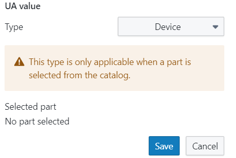
Device: This option is only available when a manufacturer-specific HX is chosen from the catalogue.
-
Expression: If preferred, a mathematical expression for the calculation of the UA value can be entered here. The same programming language as in the programmeable controller is expected
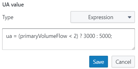
Important: Don’t forget to save the calculated UA-value. If you click somewhere else in the model before saving, the calculation will be canceled.
Heat exchanger flow type: A dropdown list of different flow types. To calculate the amount of heat transfer realised in the heat exchangers, it is important to characterize the flow type. The Optimiser supports models for the following types of flow:
-
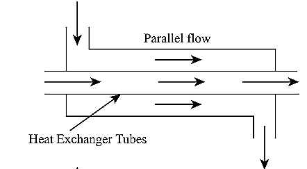
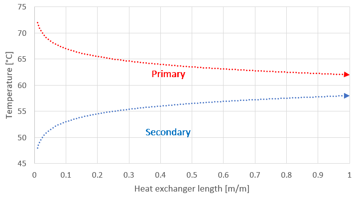
Parallel flow: Flow type where the primary and secondary streams flow in the same direction, separated by a shared wall. As they enter at the same side of the HX, the initial temperature difference between the two streams will be large and decrease gradually along the length of the HX. This way, both streams will have a nearly similar exit temperature at the end of the HX. In practice, this type of heat exchanger is not often used in heating systems, as they have a lower heat exchange effectiveness than the counter flow type heat exchanger.
-
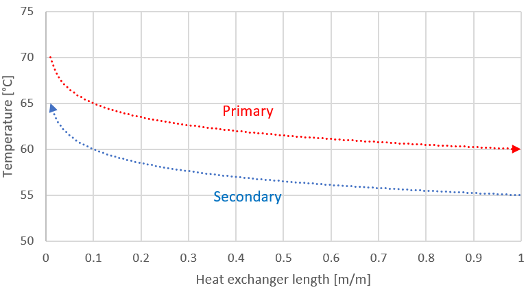
Counter flow: Flow type where the primary and secondary streams flow in the opposite direction, separated by a shared wall. As they enter at opposite sides of the HX, the temperature difference between the two streams will be more uniform along the length of the HX. This way, the HX will experience less thermal stress. Furthermore, the opposite flow movement allows the exiting temperature of the secondary stream to be higher than the exit temperature of the primary stream (something that is not possible for parallel flow HXs). In practice, this type of heat exchanger is most commonly used in heating systems, as they have a higher heat exchange effectiveness than the parallel flow type heat exchanger.
-
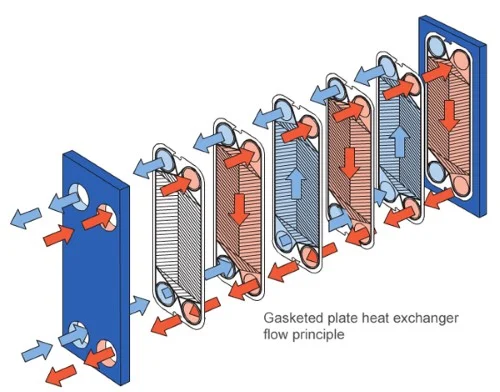
Cross flow: Flow type where the primary and secondary streams move in perpendicular directions, separated by a shared wall. Due to the perpendicular entries of the flows, their heat exchanger effectiveness is better than parallel flow, but worse than counter flow type HXs. In practice, this type of heat exchanger is often used in heating systems for its compactness. The heat exchange between both streams is two-dimensional by nature and therefore not easily illustrated in a graph.
By default, the flow type is set to ‘Counter flow’. Using the UA value and the heat flow type, the exchanged heat can be calculated for different boundary conditions.
Primary capacitance: The amount of heat that must be supplied to increase the temperature by 1 Kelvin at the primary side of the heat exchanger. By default, this value is set to 2.5 kJ/K .
If the capacitance isn't known but the water content and mass of steel are known, the user can calculate the capacitance by clicking on the "pencil" icon and enter these aspects into the capacitance calculator. The average flow temperature and type of refrigerant can also be changed. Next, click on the “Calculate”-button to calculate the capacitance.
Always press the “Save” button before closing the pop window. If you click on another component before saving, your calculation will be canceled!
Secondary capacitance: The amount of heat that must be supplied to increase the temperature by 1 Kelvin at the secondary side of the heat exchanger. By default, this value is set to 2.5 kJ/K .
Primary thermal losses: A parameter accounting for the thermal heat losses to the environment at the primary side of the heat exchanger. By default, this value is set to 1 W/K .
Secondary thermal losses: A parameter accounting for the thermal heat losses to the environment at the secondary side of the heat exchanger. By default, this value is set to 1 W/K .
Heat exchanger insulation
The heat exchanger insulation component has the following parameters:
K value: The K factor of an insulation type represents the material’s thermal conductivity. The lower the K factor, the better the insulation. By default, this parameter has a value of 0.039 W/ (m K).
Thickness: The thickness of the insulation layer. By default, this parameter has a value of 0.02 m.
By default, this parameter has a value of 25%.
Common errors
More information: Error/warning overview
|
Error message |
Solution |
|---|---|
|
Override supply temperature and secondary supply temperature are too close together |
The supply temperature before and after the heat exchanger can only become equal for an infinitely large HX. Make sure the primary supply temperature is higher than the secondary supply temperature. |
|
Override return temperature and secondary return temperature are too close together |
The return temperature before and after the heat exchanger can only become equal for an infinitely large HX. Make sure the primary return temperature is higher than the secondary return temperature. |
|
Expected the override supply temperature to be higher than the secondary supply temperature |
In order to transfer heat in the right direction. the primary supply temperature should always be higher than the secondary supply temperature. |
|
Expected the override return temperature to be higher than the secondary return temperature |
In order to transfer heat in the right direction. the primary return temperature should always be higher than the secondary return temperature. |
Heat exchanger for heating and cooling
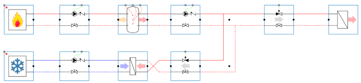
This BC is used when the main function of the HX is to extract heat from a primary (hot) side by providing cooling from the secondary (cold) side. Generally, an abundant heat source or thermal vessel is situated further upstream the primary gate, while a cooling source is situated further upstream the secondary gate. Whenever the abundant heat source must be dissipated, the cooling source is turned and extracts heat over the heat exchanger.
Note that the Optimiser expects a cooling circuit connected to the secondary gate of the BC.
In contrast to the heat exchanger for heating, design calculations are not supported for this BC. The UA-value, thermal losses, capacitances, design temperatures & heat flow should therefore be entered manually.
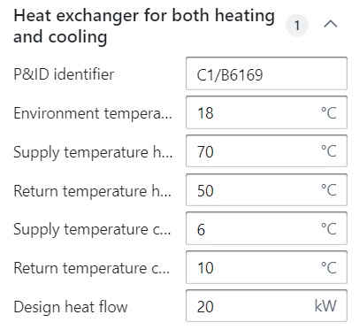
The BC itself has six parameters:
Supply temperature heating: The primary flow design temperature further upstream the primary gate. By default, this parameter has a value of 70 °C.
Return temperature heating: The primary return design temperature further upstream the primary gate. By default, this parameter has a value of 50 °C.
Environment temperature: The temperature of the room/environment in which the heat exchanger is placed. This parameter is used to take heat losses from the HX to its environment into account during simulation and is set to 18 °C by default.
Supply temperature cooling: The secondary flow design temperature further upstream the secondary gate. By default, this parameter has a value of 6 °C.
Return temperature cooling: The secondary return design temperature further upstream the secondary gate. By default, this parameter has a value of 10 °C.
Design heat flow: The designed heat flow that is extracted from the primary to the secondary side. By default, this value is set to 1 kW.
In terms of components, this BC is similar to the heat exchanger for heating. See above for the implementation of their parameters.
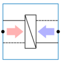
Note that the primary parameters refer to the hot side of the heat exchanger (indicated by the gate with the red arrow), while the secondary parameters refer to the cold side of the heat exchanger (indicated by the gate with the blue arrow).