
Toggle auto-connect can be used in multiple ways to minimise your drawing time. We will explain the different ways it can be used on this page.
Drawing pipes
Auto-connect can be used to draw your pipes automatically. To use this, make sure to follow the following steps:
|
Step |
Explanation |
Example |
|---|---|---|
|
1 |
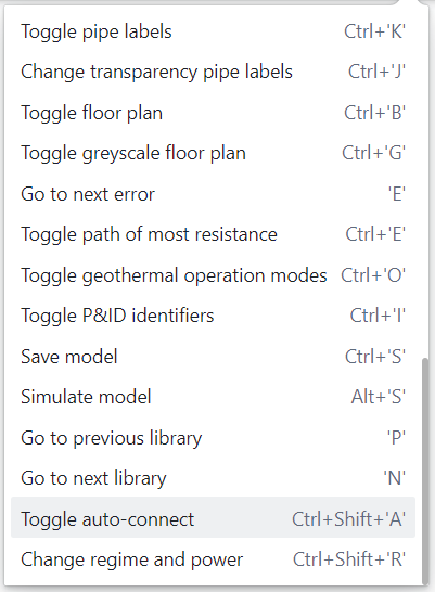
Go to the operations menu |

|
|
2 |
Make sure auto-connect is on (all the way down in the operations menu) |

|
|
3 |
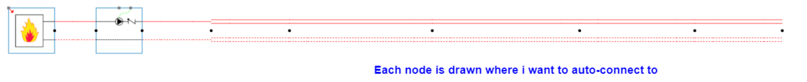
Draw each node individually where you want to connect your pipes to |
|
|
4 |
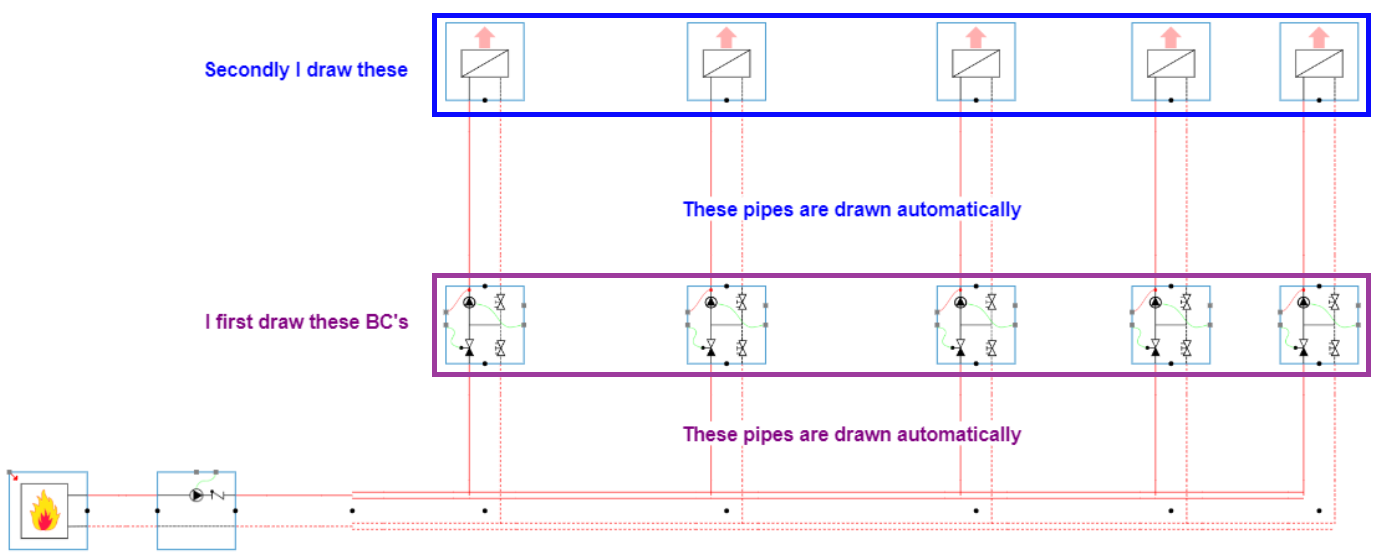
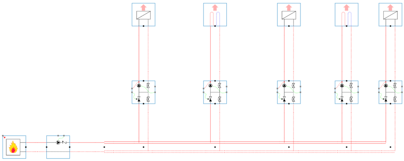
Draw the BCs which you want to automatically connect to the rest of your circuit. |
|
Drawing zones
Auto-connect can be used to draw your zones automatically. To use this, make sure to follow the following steps:
|
Step |
Explanation |
Example |
|---|---|---|
|
1 |
Go to the operations menu |
|
|
2 |
Make sure auto-connect is on (all the way down in the operations menu) |

|
|
3 |
Draw in your model with distribution circuits and end units |
|
|
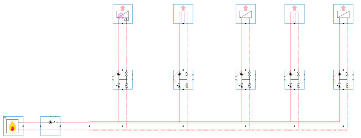
4 |
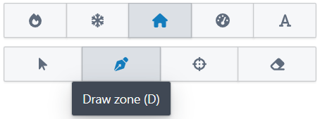
Go to the zone library end click on ‘Draw zone (D)’. The pointer of your mouse will become a purple circle with the letters ‘ZQ’ next to it. |
|
|
5 |
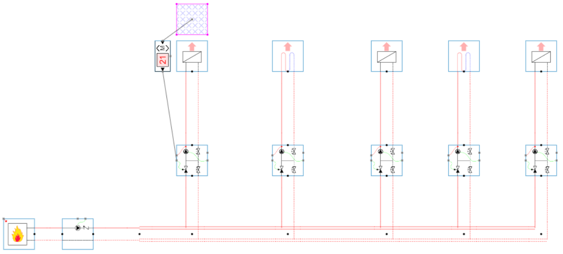
Click on the end units which you want to be connected to a zone. The end unit is automatically connected to a zone with a connected modulating room controller. |
|
|
6 |
The end unit is automatically connected to a zone with a connected modulating room controller. |
|
|
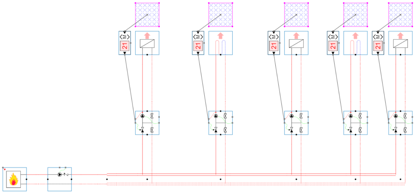
7 |
You can now do this for all the end units which you want to be assigned to a zone and controller by a controller. |
|
Drawing controllers on distribution circuits
Auto-connect can be used to draw your controllers automatically. To use this, make sure to follow the following steps:
|
Step |
Explanation |
Example |
|---|---|---|
|
1 |
Go to the operations menu |
|
|
2 |
Make sure auto-connect is on (all the way down in the operations menu) |
|
|
3 |
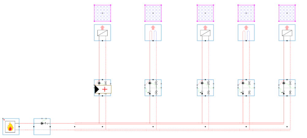
Draw in your model with distribution circuits and end units |
|
|
4 |
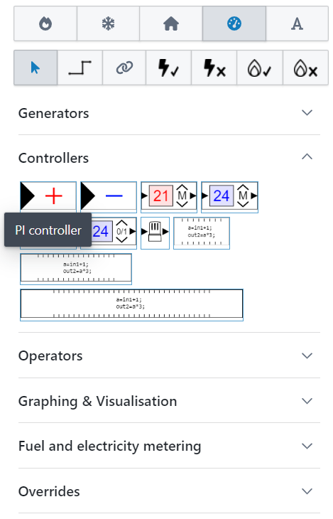
Go to the controller library and click on the PI controller. The pointer of your mouse will become a PI-controller. |
|
|
5 |
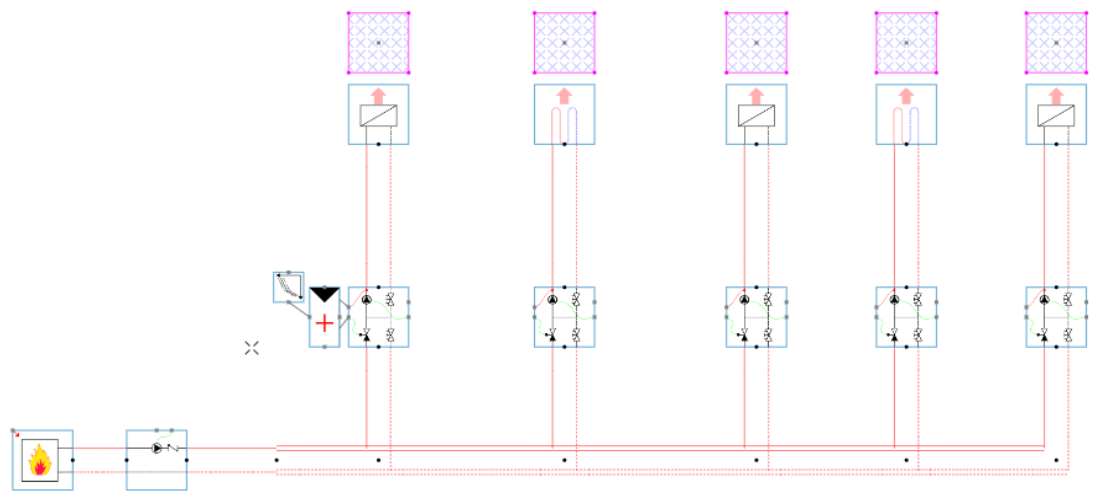
Click on the distribution circuits which you want to be controlled by a PI controller. |
|
|
6 |
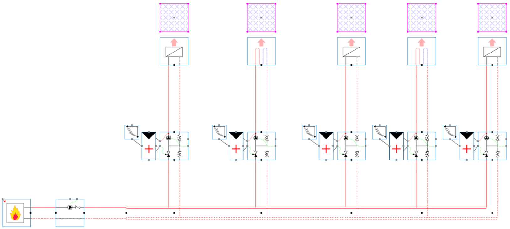
The controller is automatically connected. |
|
|
7 |
You can now do this for all the distribution circuits which you want to be controlled by a PI-controller. |
|