Control philosophy
For the main page on advanced control logic for hybrid units, see Advanced control logic for Generation III templates within the Hysopt Inspiration Library.
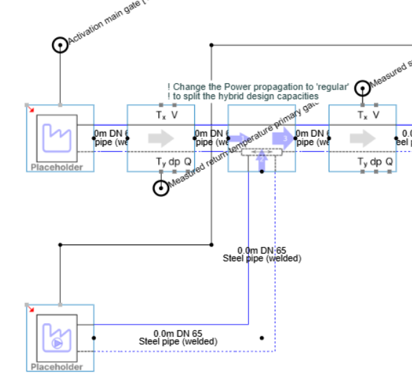
This page explains the control philosophy for the different hybrid block configurations. The advanced control logic determines when a secondary gate must be activated or deactivated to meet the required heating or cooling load. Each hybrid block type has a programmable controller with dedicated inputs and outputs. The controller structure is similar across configurations, but the detailed control philosophy depends on the hydraulic arrangement and operating mode.
General parameterisation
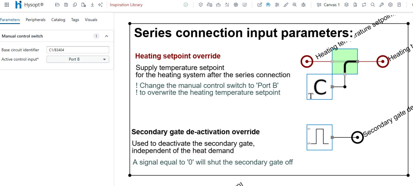
Typically, a hybrid controller includes two user-adjustable inputs:
-
Setpoint override: by default, the temperature setpoint is extracted from the secondary circuit through the Energy centre front block. To override this setpoint, set the Active control input parameter of the Manual control switch block to Port B. The controller will then read the setpoint connected to that dedicated port.
-
Gate deactivation override: by default, the hybrid block determines automatically whether the secondary gate must be activated. This input allows the user to deactivate the secondary gate manually or periodically, independently of the heat demand.
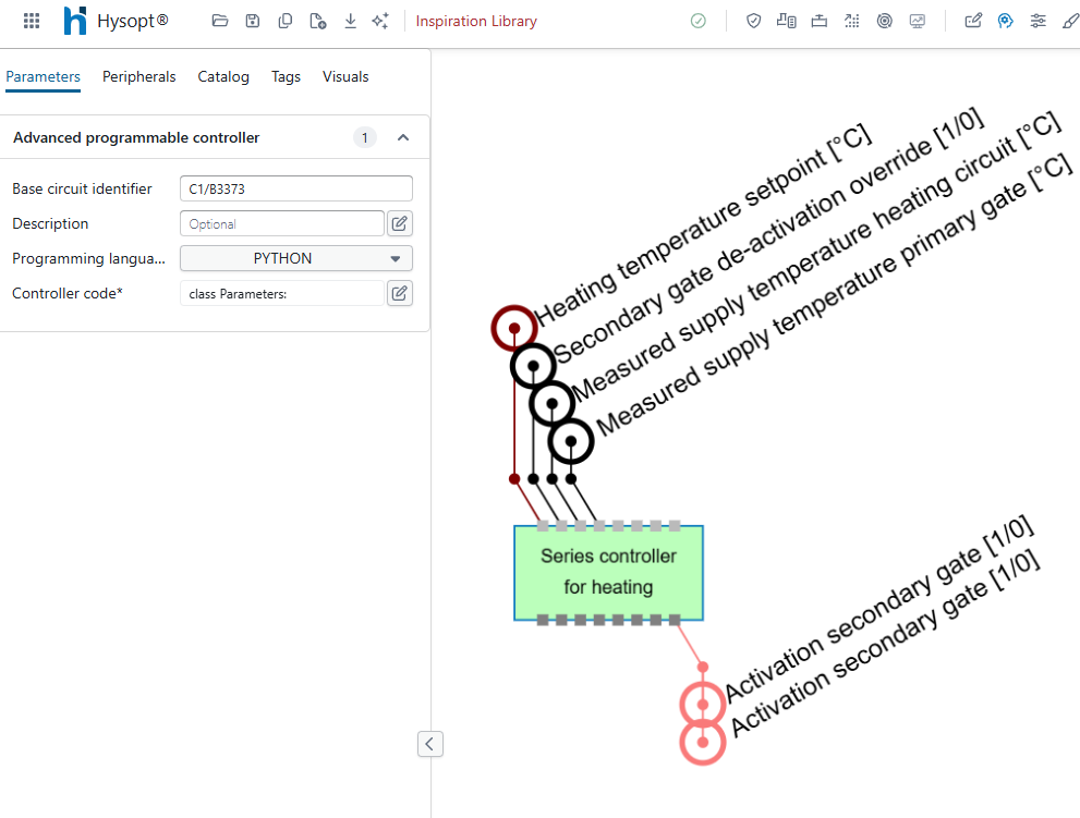
The programmable controller typically includes four input fields and one output field that do not need to be changed by the user:
-
Heating temperature setpoint and secondary gate deactivation override: these inputs come from the dedicated user input fields.
-
Measured supply temperature of the heating circuit and primary gate: these values are taken directly from the model. They are compared with the temperature setpoint to determine whether the required system temperatures are reached.
-
Activation of the secondary gate: based on the comparison between the measured values and the setpoint, the controller generates an output signal that activates or deactivates the secondary gate.
Buffer for heating
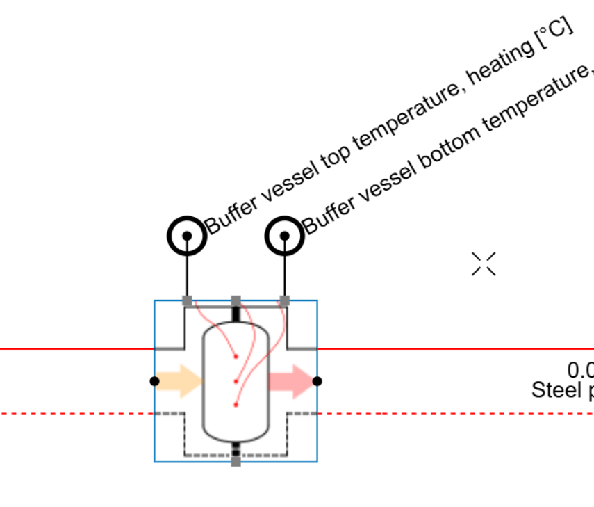
In a buffer configuration, the primary side upstream of the buffer and the secondary side downstream of the buffer are hydronically separated. The production units are located upstream of the buffer. They are activated when the temperature at the end units downstream of the buffer drops and additional heat is required.
Activation: The controller measures the temperature at the top of the buffer and compares it with the temperature setpoint. When the measured temperature falls below the setpoint, the buffer is considered discharged and the primary side is activated.
Deactivation: The controller measures the temperature at the bottom of the buffer and compares it with the temperature setpoint. When the measured temperature rises above the setpoint, the buffer is considered charged and the primary side is deactivated.
Buffer for cooling
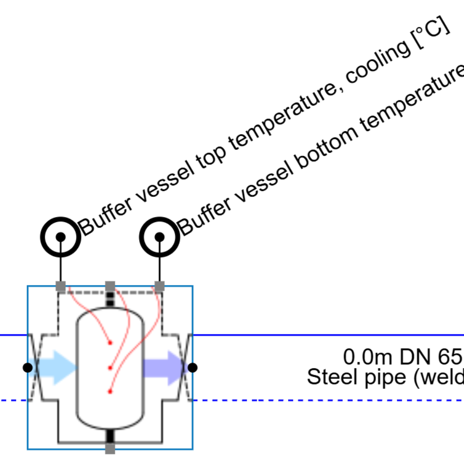
In a buffer configuration, the primary side upstream of the buffer and the secondary side downstream of the buffer are hydronically separated. The production units are located upstream of the buffer. They are activated when the temperature at the end units downstream of the buffer rises and additional cooling is required.
Activation: The controller measures the temperature at the bottom of the buffer and compares it with the temperature setpoint. When the measured temperature rises above the setpoint, the buffer is considered discharged and the primary side is activated.
Deactivation: The controller measures the temperature at the top of the buffer and compares it with the temperature setpoint. When the measured temperature falls below the setpoint, the buffer is considered charged and the primary side is deactivated.
Parallel for heating
In a parallel configuration, the flow rate of the heating circuit, indicated by arrow 3, is split between the production units at the primary gate, indicated by arrow 1, and the production units at the secondary gate, indicated by arrow 2. The secondary gate can therefore assist the production units at the primary gate when they cannot increase the flow temperature to the required setpoint.
Activation: The controller measures the temperature of the heating circuit and compares it with the temperature setpoint. When the measured temperature falls below the setpoint, the secondary gate is activated.
Deactivation: The controller measures the temperature of the heating circuit and compares it with the temperature setpoint. When the measured temperature rises above the setpoint again, the secondary gate is deactivated.
This deactivation method is not robust on its own, because the activated production units contribute to reaching the temperature setpoint. As a result, the controller can cycle the secondary gate on and off. For robust control strategies with parallel hybrid blocks, additional measurements such as system flow rate and consumed heat are required.
Parallel for cooling
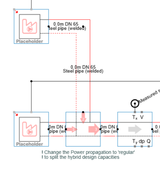
In a parallel configuration, the flow rate of the cooling circuit, indicated by arrow 3, is split between the production units at the primary gate, indicated by arrow 1, and the production units at the secondary gate, indicated by arrow 2. The secondary gate can therefore assist the production units at the primary gate when they cannot reduce the flow temperature to the required setpoint.
Activation: The controller measures the temperature of the cooling circuit and compares it with the temperature setpoint. When the measured temperature rises above the setpoint, the secondary gate is activated.
Deactivation: The controller measures the temperature of the cooling circuit and compares it with the temperature setpoint. When the measured temperature falls below the setpoint again, the secondary gate is deactivated.
This deactivation method is not robust on its own, because the activated production units contribute to reaching the temperature setpoint. As a result, the controller can cycle the secondary gate on and off. For robust control strategies with parallel hybrid blocks, additional measurements such as system flow rate and consumed cooling are required.
Series for heating
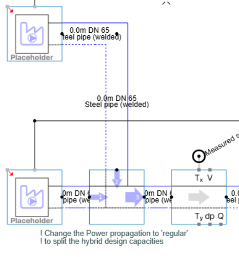
In a series configuration, the flow rate of the heating circuit, indicated by arrow 3, first passes through the production units at the primary gate, indicated by arrow 1, and then through the production units at the secondary gate, indicated by arrow 2. The secondary gate can therefore top up the supply temperature when the production units at the primary gate cannot increase the flow temperature to the required setpoint.
Activation: The controller measures the temperature of the heating circuit and compares it with the temperature setpoint. When the measured temperature falls below the setpoint, the secondary gate is activated.
Deactivation: The controller measures the temperature at the primary gate and compares it with the temperature setpoint. When the measured temperature rises above the setpoint again, the secondary gate is deactivated.
Series for cooling
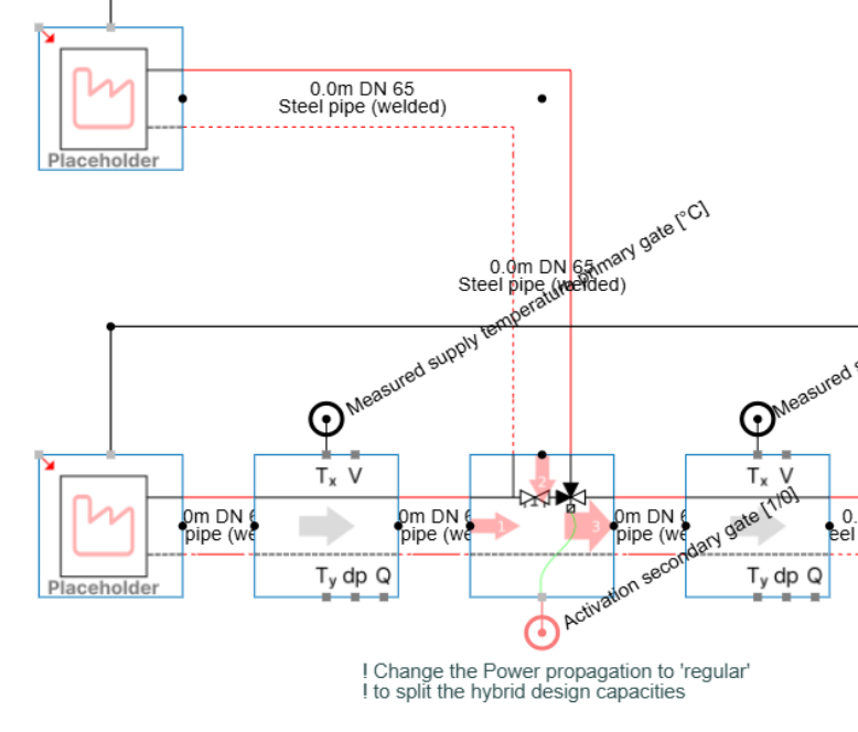
In a series configuration, the flow rate of the cooling circuit, indicated by arrow 3, first passes through the production units at the primary gate, indicated by arrow 1, and then through the production units at the secondary gate, indicated by arrow 2. The secondary gate can therefore further reduce the supply temperature when the production units at the primary gate cannot reduce the flow temperature to the required setpoint.
Activation: The controller measures the temperature of the cooling circuit and compares it with the temperature setpoint. When the measured temperature rises above the setpoint, the secondary gate is activated.
Deactivation: The controller measures the temperature at the primary gate and compares it with the temperature setpoint. When the measured temperature falls below the setpoint again, the secondary gate is deactivated.
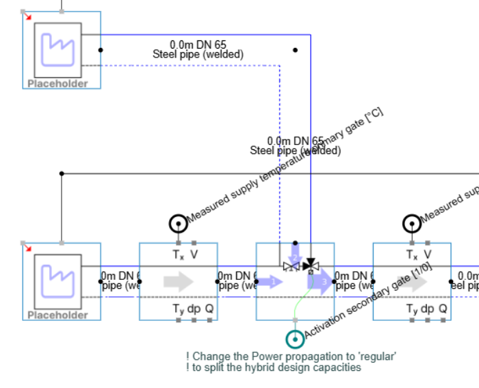
Shunt in supply for heating
In a shunt-in-supply configuration, the flow rate of the heating circuit, indicated by arrow 3, first passes through the production units at the main gate, indicated by arrow 1. It then passes through the open header on the supply line towards the production units at the shunt gate, indicated by arrow 2. The shunt gate can therefore top up the supply temperature when the production units at the main gate cannot increase the flow temperature to the required setpoint.
Activation: The controller measures the temperature of the heating circuit and compares it with the temperature setpoint. When the measured temperature falls below the setpoint, the shunt gate is activated.
Deactivation: The controller measures the temperature at the main gate and compares it with the temperature setpoint. When the measured temperature rises above the setpoint again, the shunt gate is deactivated.
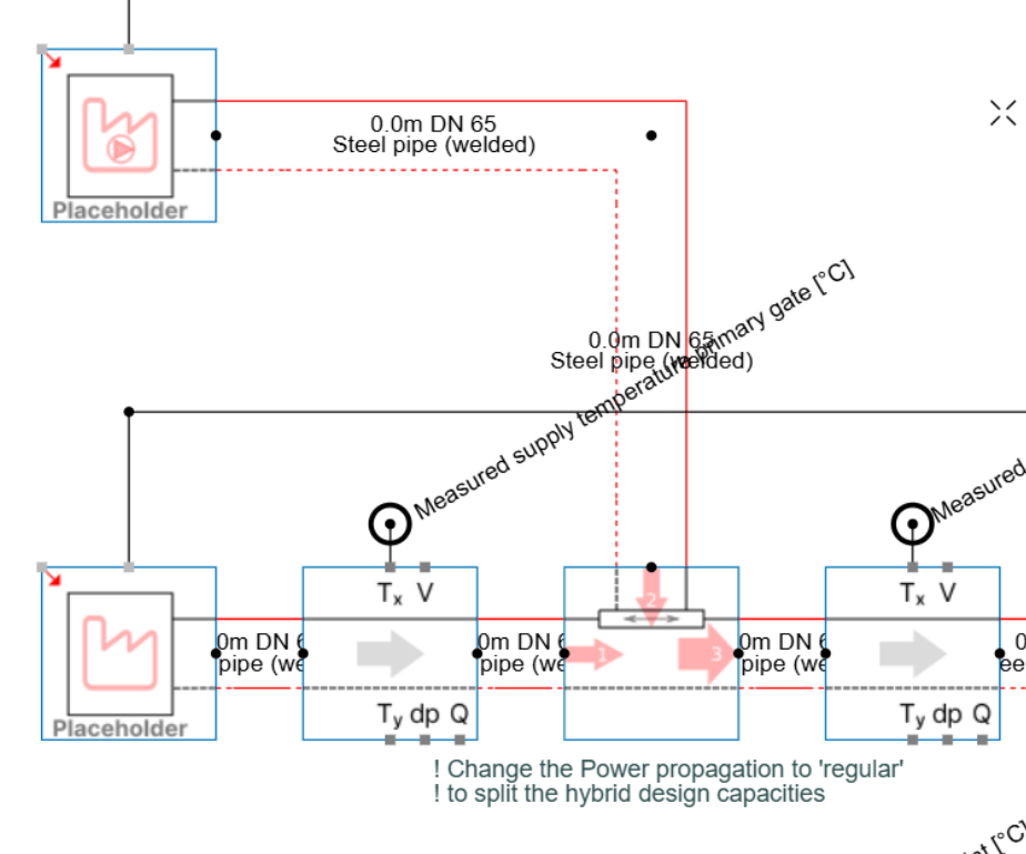
Shunt in supply for cooling
In a shunt-in-supply configuration, the flow rate of the cooling circuit, indicated by arrow 3, first passes through the production units at the main gate, indicated by arrow 1. It then passes through the open header on the supply line towards the production units at the shunt gate, indicated by arrow 2. The shunt gate can therefore further reduce the supply temperature when the production units at the main gate cannot reduce the flow temperature to the required setpoint.
Activation: The controller measures the temperature of the cooling circuit and compares it with the temperature setpoint. When the measured temperature rises above the setpoint, the shunt gate is activated.
Deactivation: The controller measures the temperature at the main gate and compares it with the temperature setpoint. When the measured temperature falls below the setpoint again, the shunt gate is deactivated.
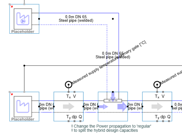
Shunt in return for heating
In a shunt-in-return configuration, the flow rate of the heating circuit, indicated by arrow 3, first passes through the open header on the return line towards the production units at the shunt gate, indicated by arrow 2. It then continues to the production units at the main gate, indicated by arrow 1. The shunt gate is prioritised for heating the return flow from the heating system. The production units at the main gate can then top up the supply temperature when the production units at the shunt gate cannot increase the flow temperature to the required setpoint.
Activation: The controller measures the temperature of the heating circuit and compares it with the temperature setpoint. When the measured temperature falls below the setpoint, the production units at the main gate are activated.
Deactivation: The controller measures the return temperature after the open header, towards the main gate, and compares it with the temperature setpoint. When the measured temperature rises above the setpoint again, the production units at the main gate are deactivated.
The shunt-in-return configuration differs from the other hybrid configurations because the production units at the shunt gate are prioritised. The controller therefore does not activate or deactivate the shunt gate, but the main gate. Because the flow rate of the heating circuit must still pass through the main gate, both gates must remain open and flow must not be blocked at the main gate while the production units at the main gate are deactivated.
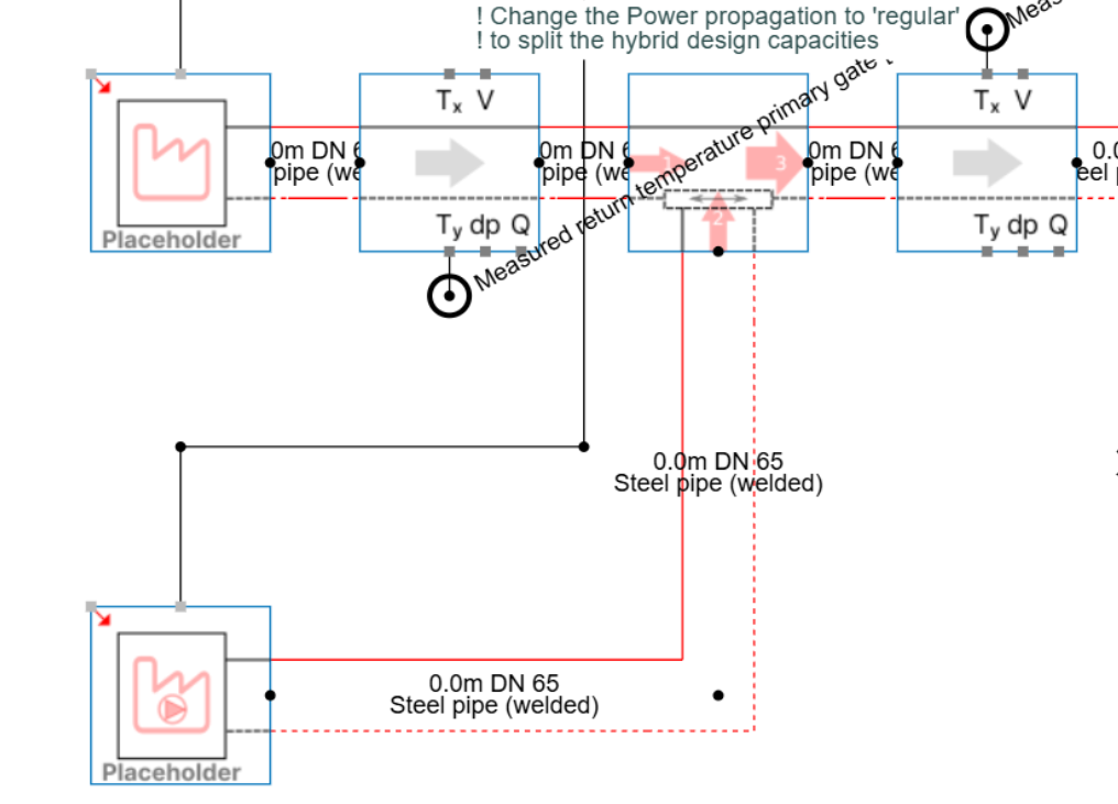
Shunt in return for cooling
In a shunt-in-return configuration, the flow rate of the cooling circuit, indicated by arrow 3, first passes through the open header on the return line towards the production units at the shunt gate, indicated by arrow 2. It then continues to the production units at the main gate, indicated by arrow 1. The shunt gate is prioritised for cooling the return flow from the cooling system. The production units at the main gate can then further reduce the supply temperature when the production units at the shunt gate cannot reduce the flow temperature to the required setpoint.
Activation: The controller measures the temperature of the cooling circuit and compares it with the temperature setpoint. When the measured temperature rises above the setpoint, the production units at the main gate are activated.
Deactivation: The controller measures the return temperature after the open header, towards the main gate, and compares it with the temperature setpoint. When the measured temperature falls below the setpoint again, the production units at the main gate are deactivated.
The shunt-in-return configuration differs from the other hybrid configurations because the production units at the shunt gate are prioritised. The controller therefore does not activate or deactivate the shunt gate, but the main gate. Because the flow rate of the cooling circuit must still pass through the main gate, both gates must remain open and flow must not be blocked at the main gate while the production units at the main gate are deactivated.