This page explains the control philosophy for heat pumps & chillers. For the main page on advanced control logic for production units, see Advanced control logic for Generation III templates within the Hysopt Inspiration Library.
For the remainder of this page, heat pumps refer to the units that operate in heating mode only. The advanced control logic determines when an activation signal and a modulation signal must be sent to each production unit.
All concepts discussed on this page also apply to chillers that operate in cooling mode only.
Heat pump control philosophy
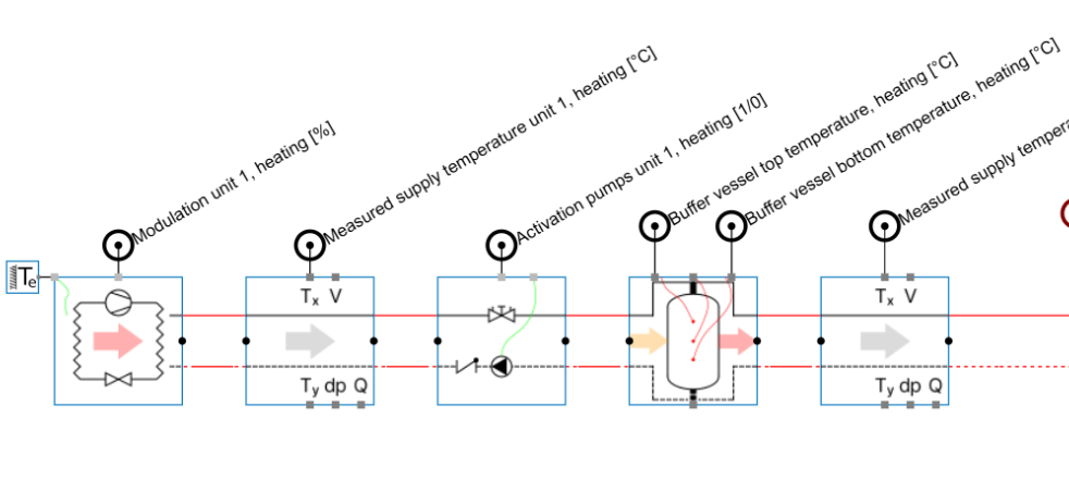
Heat pumps that operate in one mode only use a control strategy that is similar to boiler control (see: Control philosophy for gas boilers & E-boilers). The main difference is that, when a buffer vessel is available, the heat pump activation signal is determined automatically based on the buffer vessel temperatures. The heat pump cascade is activated when the buffer vessel is depleted and deactivated when the buffer is fully charged.
A secondary measurement downstream of the buffer vessel is used to verify that the supply temperature in the secondary circuit reaches the setpoint. If no buffer vessel is available, the heat pump relies on an external activation signal, similar to the boiler control strategy.
Input field
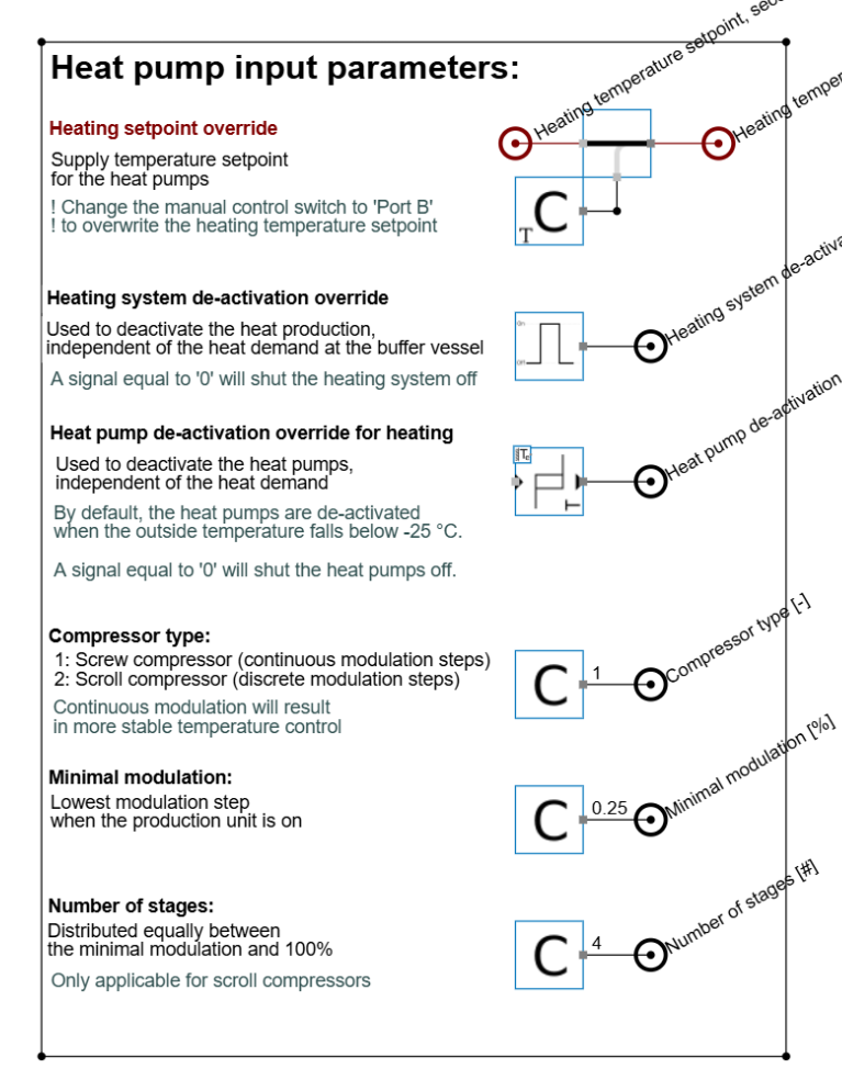
The heat pump control operation is autonomous and independent of the user’s design choices. This makes the control logic robust and reliable. The user can still tune the heat pump control behaviour through the input fields with the parameters: setpoint override, deactivation override, compressor type, minimum modulation & number of stages. A detailed description of these parameters can be found here: Control philosophy for gas boilers & E-boilers.
Additionally, heat pump templates include one additional input parameter:
-
Heat pump deactivation override: this parameter acts as a safety mechanism that can deactivate the heat pump based on the outside temperature, independently of the heat demand. By default, the threshold values are set to extremes: -25 °C for heating protection and 60 °C for cooling protection. This prevents unintended deactivation when the parameter is not in use.
Programmable controller
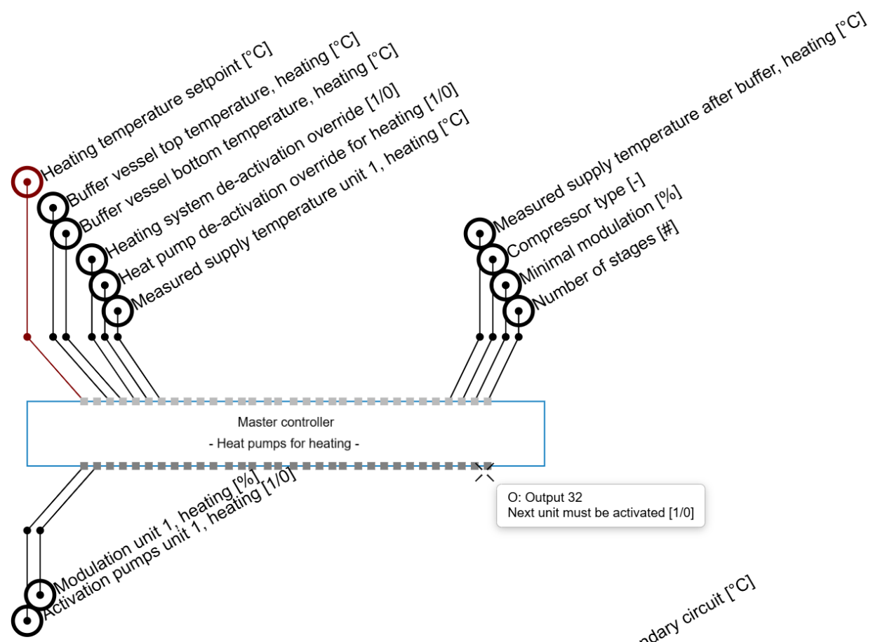
The heat pump programmable controller uses input and output fields that are similar to the boiler controller (see also: Control philosophy for gas boilers & E-boilers). The main difference is in the core setpoints. When a buffer vessel is connected, the Heat demand input is replaced by two buffer temperature measurements. The Heat demand input can still be used for manual activation or deactivation when no buffer vessel is available.
If a buffer vessel is available but cascade activation must be controlled manually through the Heat demand input, disconnect the buffer vessel temperature inputs. As long as these buffer temperature inputs remain connected, the automated control logic gives priority to the internal activation signal based on buffer temperatures rather than to the external heat demand signal.