This page explains the control philosophy for gas boiler & E-boilers. For the main page on advanced control logic for production units, see Advanced control logic for Generation III templates within the Hysopt Inspiration Library.
Gas boilers & E-boilers are thermal production units that operate in heating mode only. The advanced control logic determines when an activation signal and a modulation signal must be sent to each production unit.
Boiler control philosophy
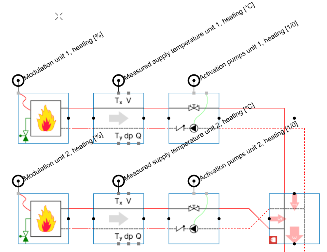
For boiler production units, the control strategy activates the boiler pumps based on an external activation signal. The supply temperature leaving the boiler is measured & used to modulate the boiler output to reach the temperature setpoint.
If the active production units are operating at full power but cannot reach the required temperature, the next boiler in the cascade is activated. If multiple units are active and operating at low modulation to avoid overshooting the setpoint, the last activated unit in the cascade is deactivated.
Input field
The boiler control operation is autonomous and independent of the user’s design choices. This makes the control logic robust and reliable. The user can still tune the boiler control behaviour through five input fields.
-
Setpoint override: by default, the temperature setpoint is extracted from the secondary circuit through the Energy centre front block. To override this setpoint, set the Active control input parameter of the Manual control switch block to Port B. The controller will then read the setpoint connected to that dedicated port.
-
Deactivation override: by default, the production block automatically determines whether the production units must be active. This input allows the user to deactivate production manually or periodically, independently of the heat demand.
-
Modulation type: by default, the boiler can use a continuous modulation signal between 0% and 100%. If the production unit must operate with discrete modulation steps, change this parameter accordingly.
-
Minimum modulation: the lowest accepted modulation level when the production unit is active. By default, this value is set to 25%.
-
Number of stages: this input is only applicable when the production unit operates with discrete modulation steps. It defines the available modulation stages. Each step is distributed evenly between the minimum modulation level and 100%.
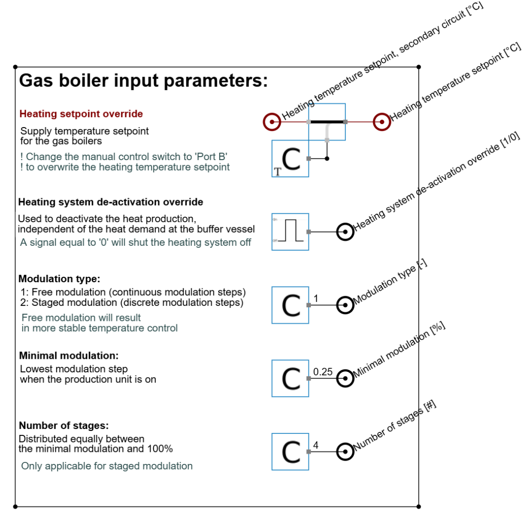
Detailed view of the input fields for a gas boiler.
Programmable controller
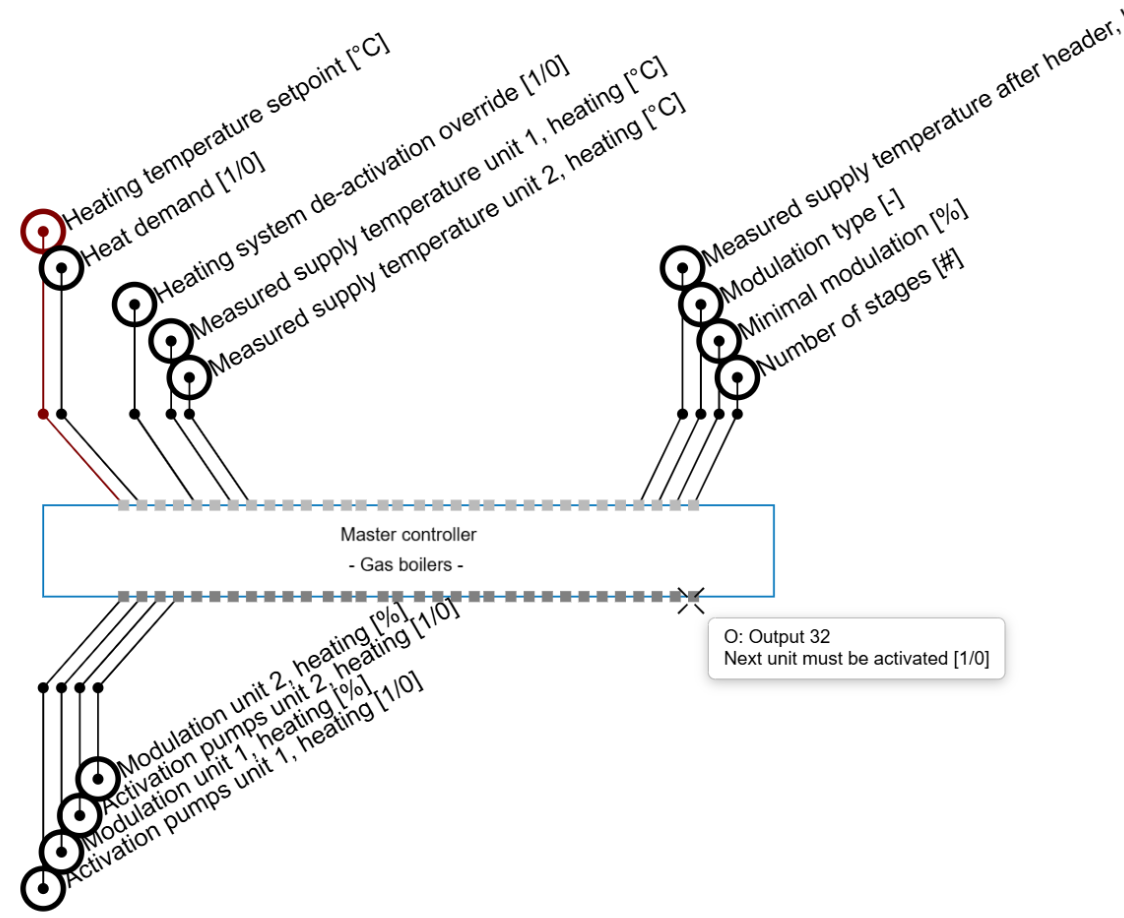
The programmable controller contains several input fields, grouped into three categories:
-
Core setpoints: this category includes the temperature setpoint and heat demand. These are the main setpoints used by the controller. The temperature setpoint is taken from the input fields. Heat demand is an external signal that must be provided by the user, or is taken from the Energy centre front.
-
Cascade measurements: this category includes the measured supply temperatures. Each production unit in the cascade should have a supply temperature connected to the controller. The automated controller can support a production cascade of up to 15 units. The cascade is prioritised based on the position of the temperature connection. For example, in a two-unit cascade, the unit connected to the Unit 1 inputs is prioritised, while the unit connected to the Unit 2 inputs acts as the secondary unit.
-
Other inputs: this category includes the remaining controller inputs. These are mainly secondary user inputs and system measurements used to maintain stable and optimal control behaviour.
The programmable controller also contains several output fields, grouped into two categories:
-
Production unit control: this category includes activation signals for the production unit and its dedicated pumps, as well as the modulation signals for that unit. As with the input fields, the production unit control outputs can support a cascade of up to 15 units. Make sure the outputs for Unit X correspond to the same production unit whose temperature measurement is connected to the Unit X input.
-
Cascade logic control: the final two outputs indicate whether the last unit in the cascade is active and whether the next unit must be activated. These outputs show when all units in the current cascade are operating and whether additional production capacity is required to reach the system temperature setpoints. The final signal can also be used as the demand signal for a second production controller in the system.