Advanced control logic for Generation III templates
All Generation III templates are supported by advanced automated control logic. These robust control strategies require only limited user input before simulations can be performed. The control logic may look complex at first, but the same patterns are used across many templates. Users are therefore encouraged to review the control logic description carefully when working with automated control templates for the first time.
End units
When the end units are not the core aspect of the templates, a generic end unit block is used. These are single-unit blocks that represent an unspecified equivalent pool of end users. During simulation, a representative heat demand is automatically imposed on the block without any required action from the user.
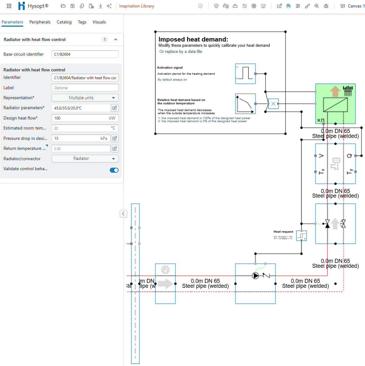
The imposed heat load is determined by three parameters:
-
Design capacity: the design capacity entered in the end-unit block. This value should be adjusted when the template is inserted into the model. It is extracted from the block by the Design values extractor base circuit.
-
Relative heat demand: a demand curve between 0 and 1 as a function of outside temperature. A value of 1 means that 100% of the design capacity is required. A value of 0 means that no heat load is required.
-
Activation signal: a time-based signal that activates the heat demand. By default, the heat demand is always active.
When calibrating a demand profile, adjust the relative heat demand and the activation signal. The design capacity is a static parameter and should not be changed during calibration, because it represents the installed heating capacity.
Hybrid blocks
When a hybrid block, such as a series, parallel, or shunt configuration, is the main focus of a template, the control logic is usually built around a dedicated programmable controller with specific input parameters.
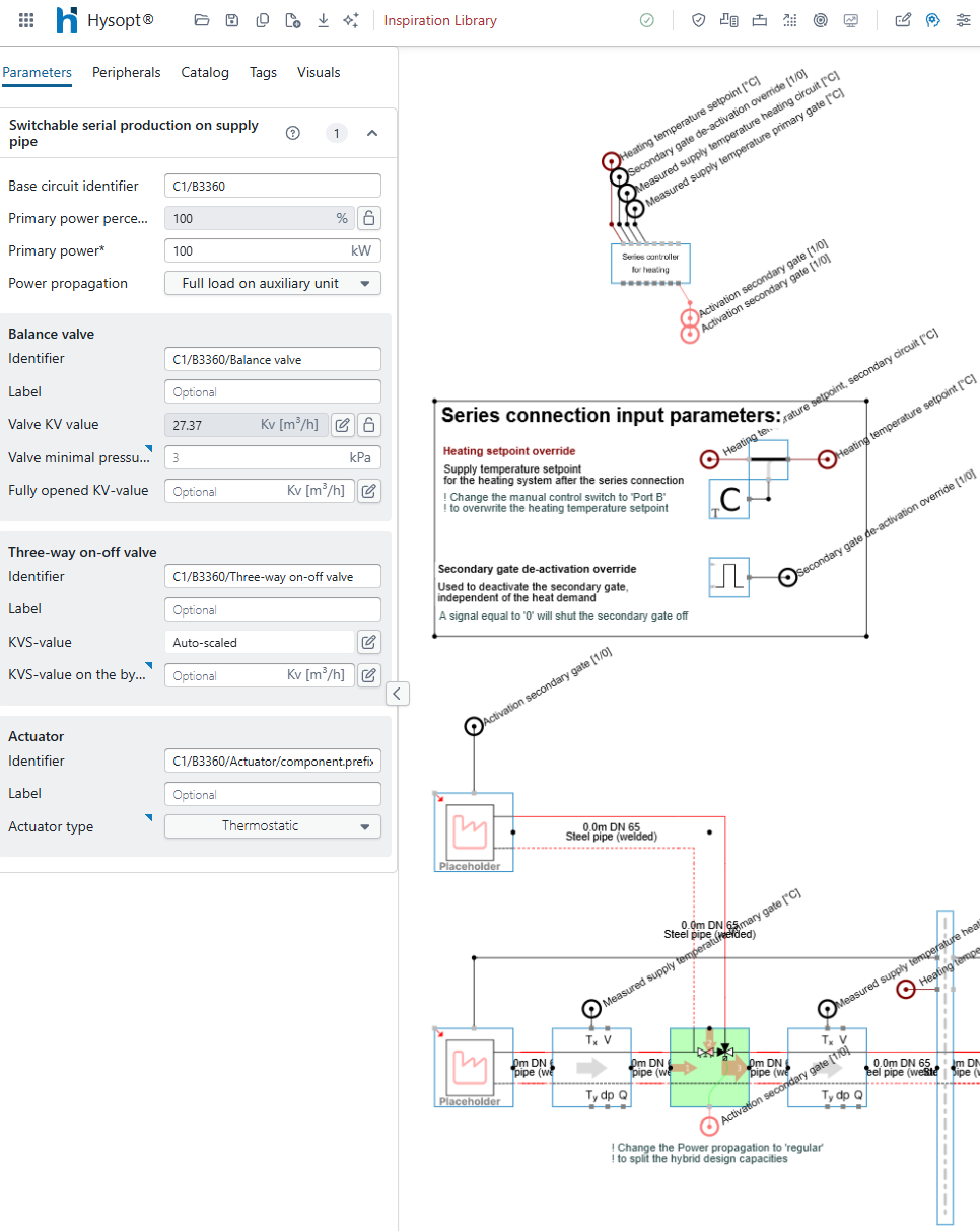
Hybrid blocks always contain a prioritised gate and a secondary gate. The hybrid control logic determines whether the secondary gate must be activated or deactivated to supply the required heat load. Each hybrid block type has its own programmable controller with dedicated inputs and outputs, but the controller structure is similar across the different configurations.
Typically, a hybrid controller includes two user-adjustable inputs:
-
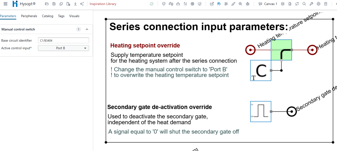
Setpoint override: by default, the temperature setpoint is extracted from the secondary circuit through the Energy centre front block. To override this setpoint, set the Active control input parameter of the Manual control switch block to Port B. The controller will then read the setpoint connected to that dedicated port.
-
Gate deactivation override: by default, the hybrid block determines automatically whether the secondary gate must be activated. This input allows the user to deactivate the secondary gate manually or periodically, independently of the heat demand.
The programmable controller typically includes four input fields and one output field that do not need to be changed by the user:
-
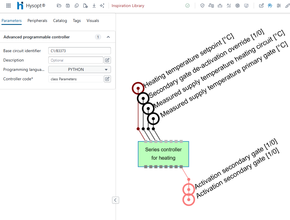
Heating temperature setpoint and secondary gate deactivation override: these inputs come from the dedicated user input fields.
-
Measured supply temperature of the heating circuit and primary gate: these values are taken directly from the model. They are compared with the temperature setpoint to determine whether the required system temperatures are reached.
-
Activation of the secondary gate: based on the comparison between the measured values and the setpoint, the controller generates an output signal that activates or deactivates the secondary gate.
Production blocks
Automated production controllers determine which production units in a cascade must be activated and how much power each unit must produce to reach the temperature setpoint. Each production block type has a dedicated programmable controller with its own inputs and outputs, but the core structure is similar across the different production technologies.
Boilers
For boiler production units, the control strategy activates the boiler pumps based on an external activation signal, measures the supply temperature leaving the boiler, and modulates the boiler output to reach the temperature setpoint. If the active production units are operating at full power but cannot reach the required temperature, the next boiler in the cascade is activated. If multiple units are active and operating at low modulation to avoid overshooting the setpoint, the last activated unit in the cascade is deactivated.
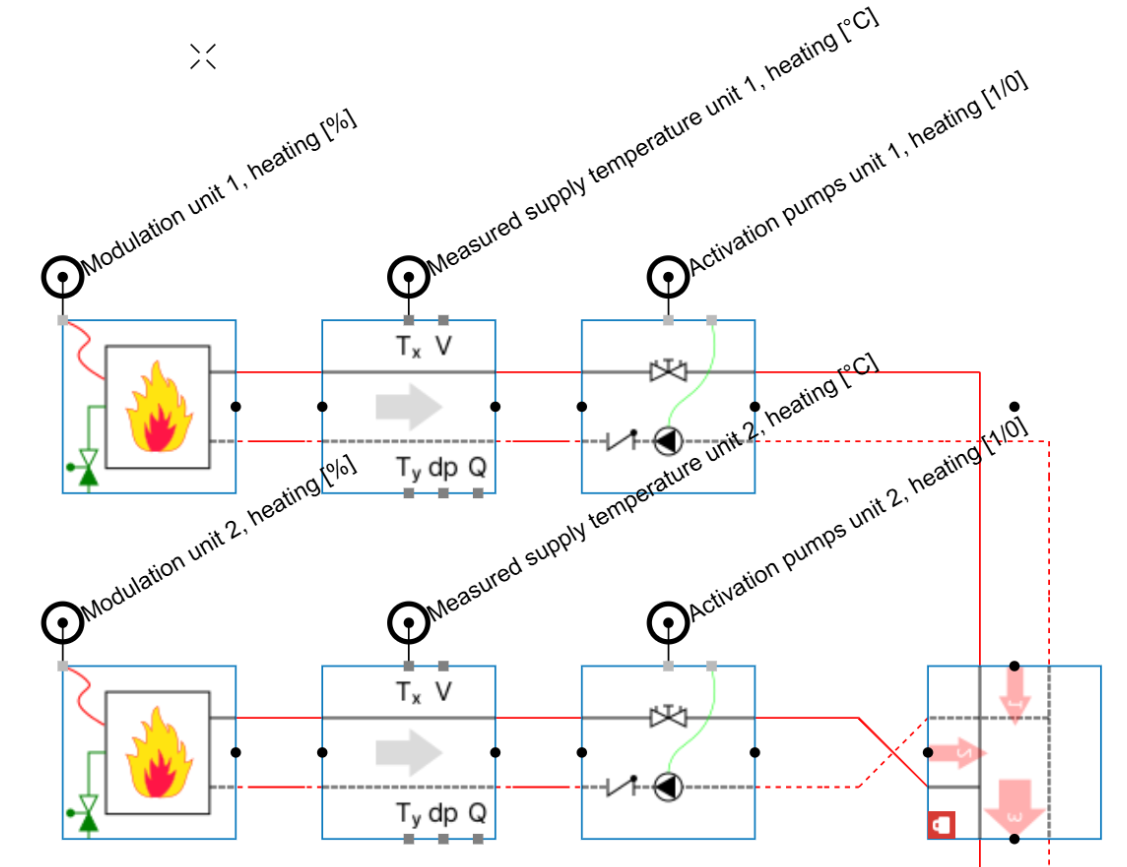
The boiler control operation is autonomous and independent of the user’s design choices. This makes the control logic robust and reliable. The user can still tune the boiler control behaviour through five input fields.
-
Setpoint override: by default, the temperature setpoint is extracted from the secondary circuit through the Energy centre front block. To override this setpoint, set the Active control input parameter of the Manual control switch block to Port B. The controller will then read the setpoint connected to that dedicated port.
-
Deactivation override: by default, the production block automatically determines whether the production units must be active. This input allows the user to deactivate production manually or periodically, independently of the heat demand.
-
Modulation type: by default, the boiler can use a continuous modulation signal between 0% and 100%. If the production unit must operate with discrete modulation steps, change this parameter accordingly.
-
Minimum modulation: the lowest accepted modulation level when the production unit is active. By default, this value is set to 25%.
-
Number of stages: this input is only applicable when the production unit operates with discrete modulation steps. It defines the available modulation stages. Each step is distributed evenly between the minimum modulation level and 100%.
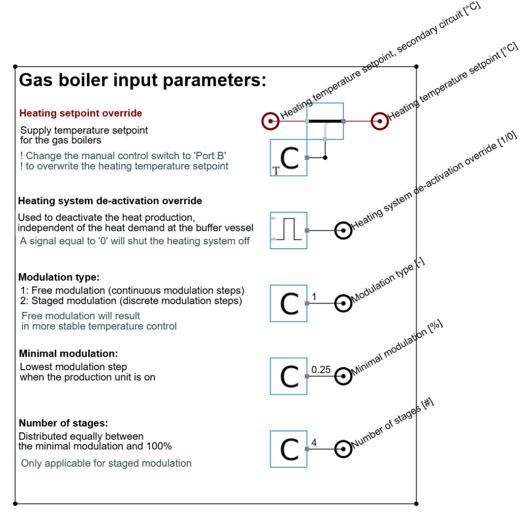
Detailed view of the input fields for a gas boiler.
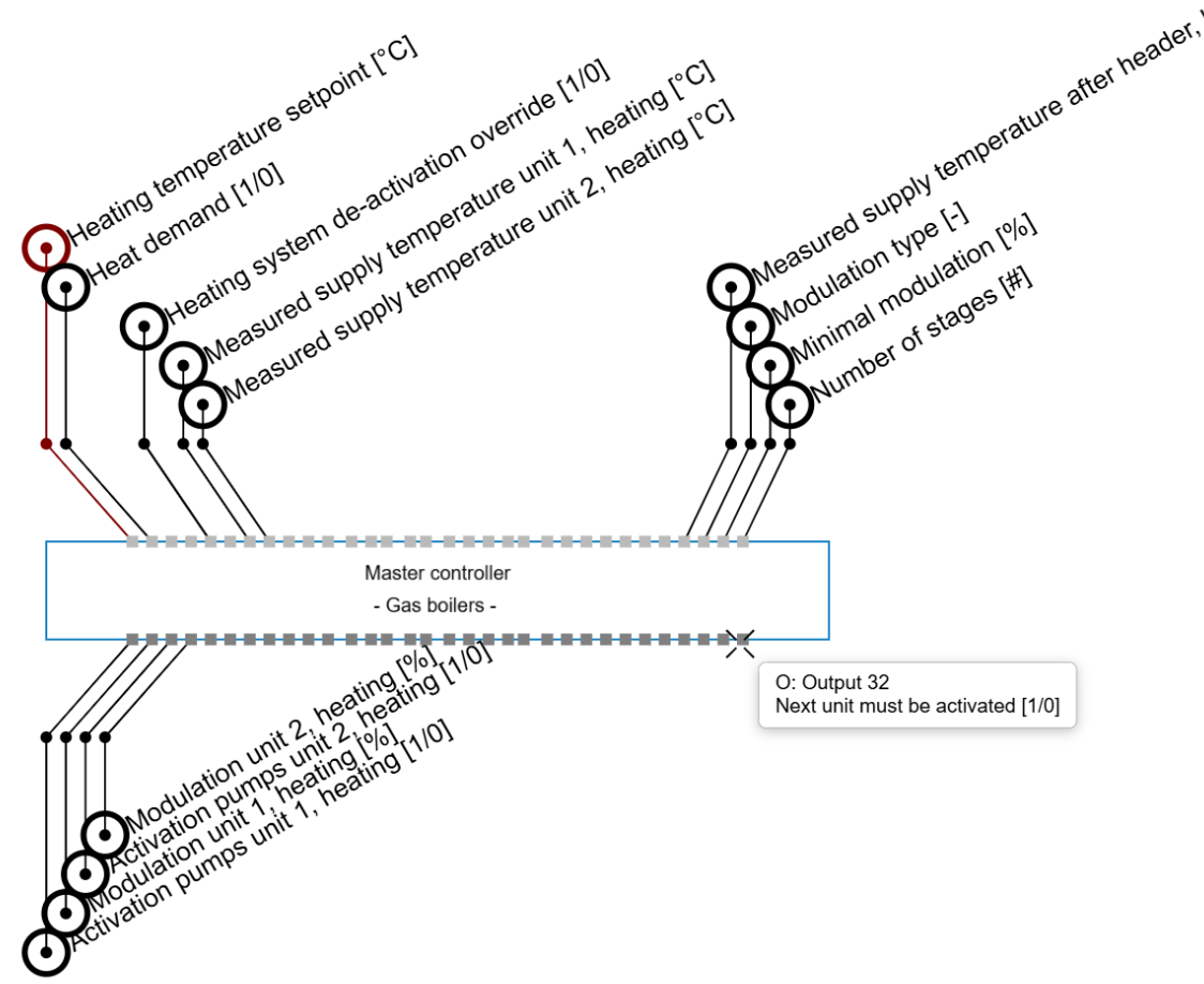
The programmable controller contains several input fields, grouped into three categories:
-
Core setpoints: this category includes the temperature setpoint and heat demand. These are the main setpoints used by the controller. The temperature setpoint is taken from the input fields. Heat demand is an external signal that must be provided by the user, or is taken from the Energy centre front.
-
Cascade measurements: this category includes the measured supply temperatures. Each production unit in the cascade should have a supply temperature connected to the controller. The automated controller can support a production cascade of up to 15 units. The cascade is prioritised based on the position of the temperature connection. For example, in a two-unit cascade, the unit connected to the Unit 1 inputs is prioritised, while the unit connected to the Unit 2 inputs acts as the secondary unit.
-
Other inputs: this category includes the remaining controller inputs. These are mainly secondary user inputs and system measurements used to maintain stable and optimal control behaviour.
The programmable controller also contains several output fields, grouped into two categories:
-
Production unit control: this category includes activation signals for the production unit and its dedicated pumps, as well as the modulation signals for that unit. As with the input fields, the production unit control outputs can support a cascade of up to 15 units. Make sure the outputs for Unit X correspond to the same production unit whose temperature measurement is connected to the Unit X input.
-
Cascade logic control: the final two outputs indicate whether the last unit in the cascade is active and whether the next unit must be activated. These outputs show when all units in the current cascade are operating and whether additional production capacity is required to reach the system temperature setpoints. The final signal can also be used as the demand signal for a second production controller in the system.
Heat pumps for one mode only
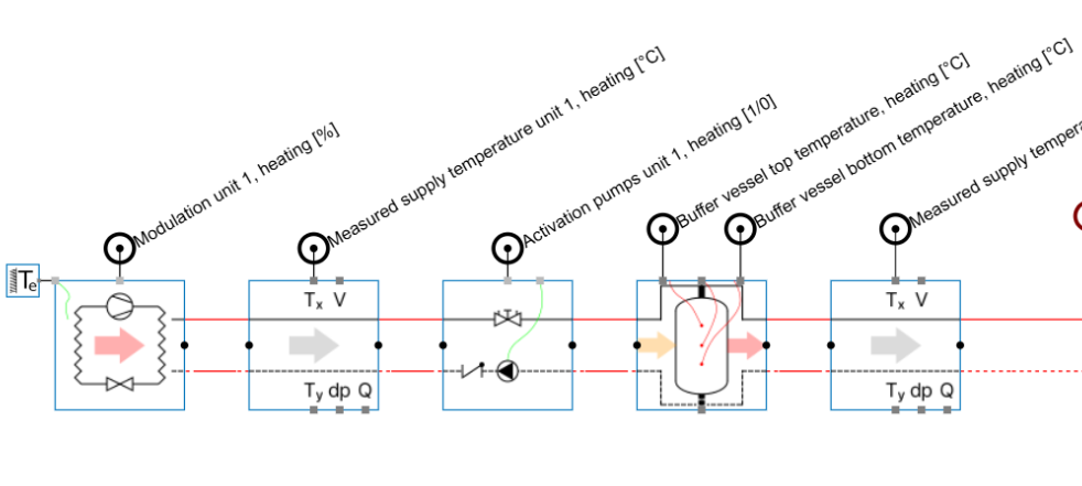
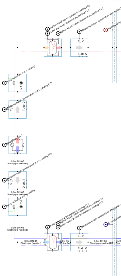
Air source heat pumps that operate in one mode only use a control strategy that is similar to boiler control. The main difference is that, when a buffer vessel is available, the heat pump activation signal is determined automatically based on the buffer vessel temperatures. The heat pump cascade is activated when the buffer vessel is depleted and deactivated when the buffer is fully charged.
A secondary measurement downstream of the buffer vessel is used to verify that the supply temperature in the secondary circuit reaches the setpoint. If no buffer vessel is available, the heat pump relies on an external activation signal, similar to the boiler control strategy.
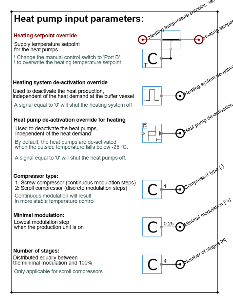
Heat pump templates include one additional input parameter:
-
Heat pump deactivation override: this parameter acts as a safety mechanism that can deactivate the heat pump based on the outside temperature, independently of the heat demand. By default, the threshold values are set to extremes: -25 °C for heating protection and 60 °C for cooling protection. This prevents unintended deactivation when the parameter is not in use.
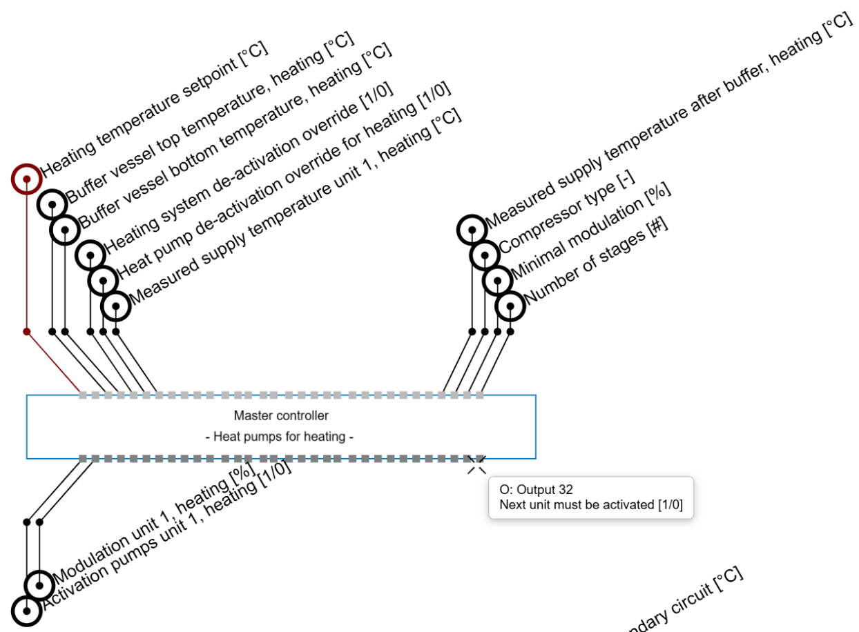
The heat pump programmable controller uses input and output fields that are similar to the boiler controller. The main difference is in the core setpoints. When a buffer vessel is connected, the Heat demand input is replaced by two buffer temperature measurements. The Heat demand input can still be used for manual activation or deactivation when no buffer vessel is available.
If a buffer vessel is available but cascade activation must be controlled manually through the Heat demand input, disconnect the buffer vessel temperature inputs. As long as these buffer temperature inputs remain connected, the automated control logic gives priority to the internal activation signal based on buffer temperatures rather than to the external heat demand signal.
Reversible heat pumps
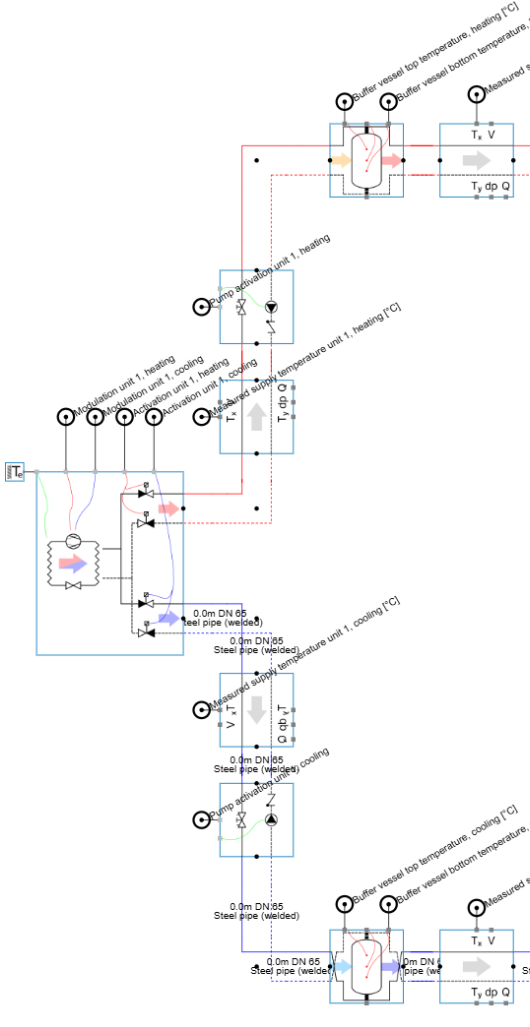
Reversible air source heat pumps can operate in both heating and cooling mode. Their control strategy is similar to the strategy used for one-mode heat pumps, but includes additional logic to determine the active operating mode. When the heat pump operates in heating mode, the cooling side must be deactivated, and vice versa. If both heating and cooling demand are present at the same time, the controller uses the selected priority mode to determine which demand is served.
Reversible heat pump templates use the same input parameters as one-mode heat pump templates, but most parameters are duplicated because the controller must consider both heating and cooling operation. In addition, reversible heat pumps include one extra input parameter:
-
Leading mode unit X: this parameter determines whether heating or cooling is prioritised for a specific production unit. When heating is prioritised, the heat pump can only operate in cooling mode if there is no heat demand, or if the unit is not required in heating mode within the production cascade. In a cascade, each production unit has its own leading mode parameter.
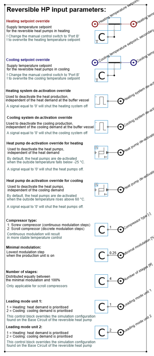
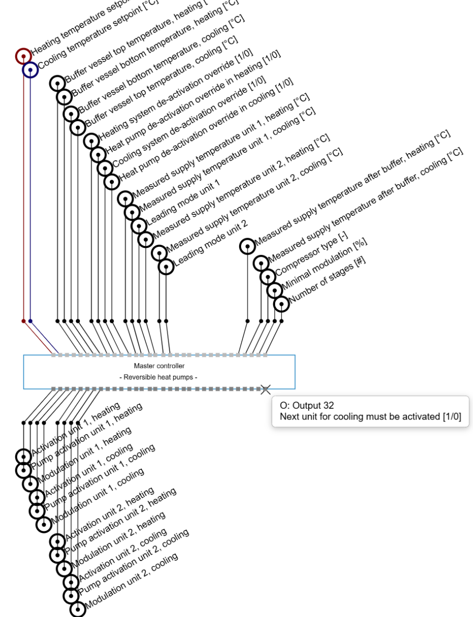
The programmable controller for reversible heat pumps works in a similar way to the controller for one-mode heat pumps, but setpoints and input parameters are required for both heating and cooling. Because the number of inputs is higher, reversible heat pump controllers can only support a cascade of up to five units. If more units are required, use the Cascade logic control outputs to activate an additional controller.
Compared with one-mode heat pumps, reversible production units have one additional input related to the leading mode of the unit. The automated controller uses an internal cascade hierarchy for heating and cooling priority. Heating priority is applied from top to bottom, meaning that the first production unit in the cascade is considered the leading unit in heating mode. Cooling priority is applied from bottom to top, meaning that the last production unit in the cascade is considered the leading unit in cooling mode. If different reversible heat pumps in a cascade have different priorities, connect the heat pumps so that the top units have heating priority and the bottom units have cooling priority.
As with one-mode heat pumps, reversible heat pumps have two output parameters per mode related to the activation of the final production unit in the cascade and the activation signal for the next production unit or cascade.
Water source heat pumps
Water source heat pumps that operate simultaneously in heating and cooling use a control strategy similar to air source heat pumps, with additional logic for heat dump availability. Because these heat pumps normally require both heating and cooling demand to operate, the controller determines the prioritised operating mode and whether unused heating or cooling can be rejected through cooling towers, dry coolers, or other dump units.
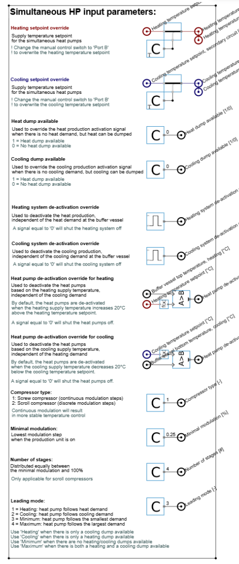
Simultaneous heat pump templates include three additional input parameters:
-
Heat or cooling dump available: without a dump, the simultaneous heat pump can only operate when both heating and cooling demand are present. In that case, the heat pump will not deliver heating or cooling in the prioritised mode if there is no demand in the non-leading mode. If a cooling tower, dry cooler, or similar dump unit is connected, this should be defined as an available dump. The heat pump can then ignore the demand signal in the non-leading mode and assume that the unused heating or cooling is rejected through the dump.
-
Heat pump deactivation override for heating or cooling: this parameter acts as a safety trigger to avoid temperatures that are too high or too low in the non-leading heating or cooling circuit. Even when a dump is available, the heat pump is deactivated if the difference between the measured temperature and the temperature setpoint exceeds the defined offset. By default, this offset is set to an extreme value: +20 °C in heating mode and -20 °C in cooling mode. This prevents unintended deactivation during normal operation when this parameter is not in use.
-
Leading mode: unlike air source heat pumps, a water source heat pump cascade can only have one leading mode. In heating mode, the controller focuses on the heating circuit and ensures that the heating temperature setpoint is reached, without checking whether the cooling temperature setpoint is reached or exceeded. In cooling mode, the same principle applies to the cooling circuit. In Minimum mode, the controller considers both circuits and operates at the lowest required power until either the heating or cooling setpoint is reached, helping to avoid setpoint overshoot. In Maximum mode, the controller also considers both circuits, but operates at the highest required power until both setpoints are reached, even if one setpoint is exceeded. Use Minimum mode when no dumps are available. Use Maximum mode when dumps are available on both the condenser and evaporator sides. If a dump is only available on the condenser side, use Cooling mode. If a dump is only available on the evaporator side, use Heating mode.