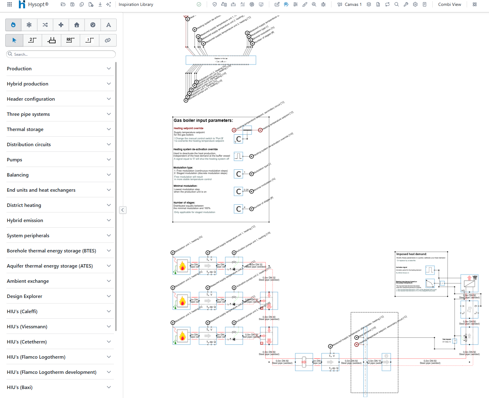
Building a model from scratch
The following workflow focuses on Generation III templates. These automated control models allow users to build complete HVAC models efficiently by combining modular, pre-configured building blocks from the Inspiration Library.
The secondary system
Although HVAC modelling and engineering often focus on the energy centre, Hysopt analysis is most effective when the secondary system is modelled first. In many projects, limited information is available about the end-unit side of the HVAC system, or its detailed layout is outside the project scope. However, a working Hysopt simulation requires a closed-loop system. This means that a high-level secondary system must be included, together with an estimated building load profile.
To create a secondary side from the Inspiration Library, follow the steps below.
Selecting a template
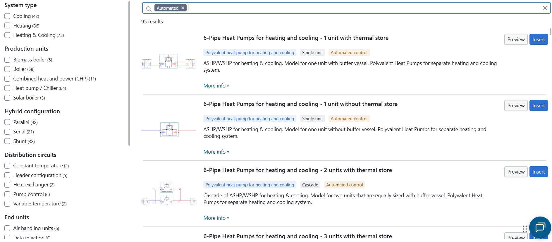
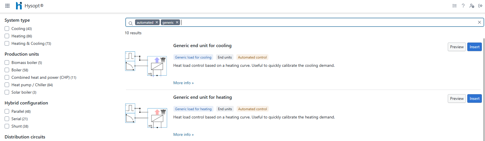
When opening a new model, open the Hysopt Inspiration Library through the Wizard. It is recommended to immediately filter the available templates by typing Automated in the search bar and pressing Enter. This removes older-generation templates from the results and shows the Generation III templates.
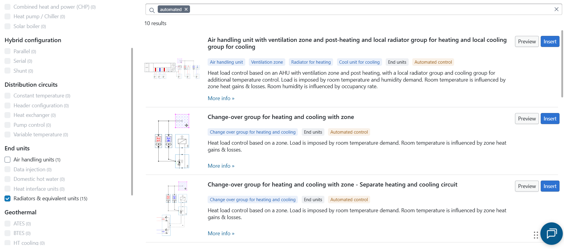
Next, select a template that matches the secondary side of the system. Use the checkboxes under End units to filter by end-unit type. Templates such as Air handling units, Radiators & equivalent units and Data injection can be used when information is available about the secondary system.
Insert the selected template into the model.
Calibration of the secondary side
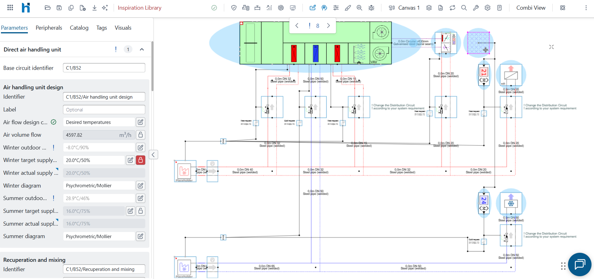
Generation III models can be divided into two parts: the production side and the end-unit side. In end-unit templates, the production side is represented by an energy centre placeholder. This placeholder acts as an idealised production unit, so the user can focus on the secondary system before defining the actual production system.
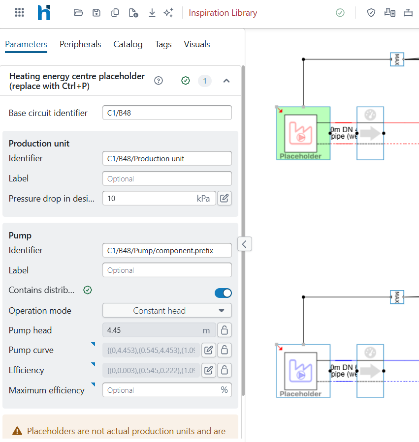
Focus first on the end-unit side. Enable Input view and fill in the required parameters of the end-unit blocks to represent the secondary system. After this, run the standard Hysopt calculation steps and simulate the model. At this stage, the detailed energy centre does not yet need to be modelled. The placeholder delivers the required heat load, allowing the secondary side to be calibrated independently from the production system.
If no detailed information is available for the end units, or if the secondary side is outside the project scope, use the generic heating or cooling end-unit templates in the Inspiration Library. These single-unit blocks represent an equivalent group of end users and can be calibrated quickly to create a representative heating or cooling demand profile.
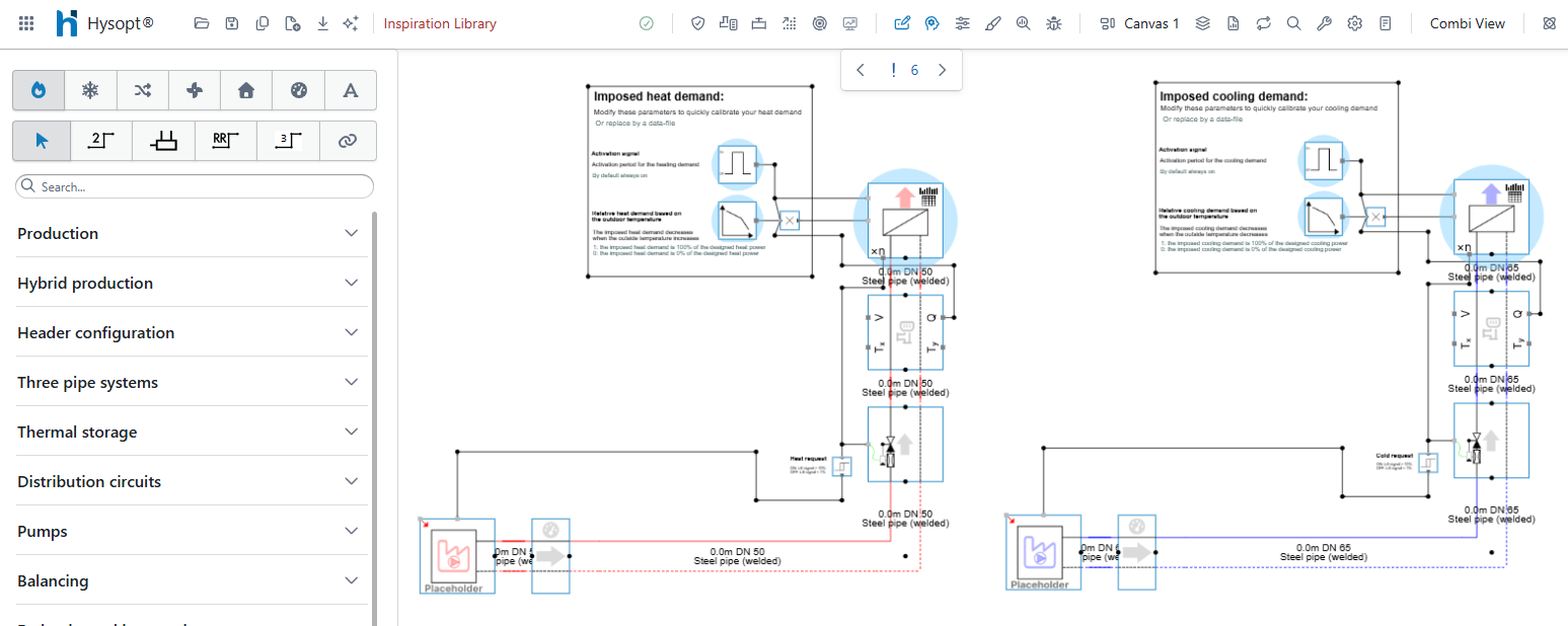
To create an equivalent secondary system, fill in the following parameters:
-
Temperature regime and design capacity: define the expected supply and return temperatures and the design heat flow entering the energy centre.
-
Activation signal and relative heat demand: define the expected operating period and the expected load profile. The relative heat demand is defined with a curve between 0 and 1 as a function of the outside temperature. A value of 1 means that 100% of the design capacity is required. A value of 0 means that no heat load is required.
After these parameters have been defined, run the standard Hysopt calculation steps and simulate the model.
The primary system
After calibrating the secondary system, use the Inspiration Library to add the production centre. Open the Wizard again and filter the results to show Generation III templates by typing Automated in the search bar and pressing Enter. Further refine the results with the checkboxes or by adding short search terms, such as Gas, 3 or Cascade.

Insert the required production template into the model. As with the end-unit templates, Generation III production templates contain both a production side and an end-unit side. In this case, the end-unit side is represented by a generic end unit and is separated from the production side by the Energy centre front block. Connect the Energy centre front to the calibrated secondary side of the model to complete the integration of the production template.