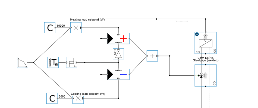
The hydraulic parameters are conform the changeover end unit with zone. The fundamental difference lies entirely in how the unit behaves during dynamic simulation, because these units are designed to operate based on an externally imposed load rather than an internal room‑temperature controller.
1. External load as primary driver
These end‑units typically receive a generic load signal (in W) from an external source such as:
-
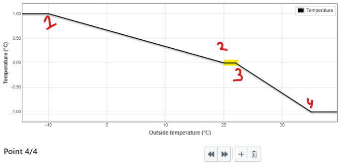
outdoor temperature (heating curve) - see picture below, yellow is deadband zone required between heating and cooling operation.
-
building simulation model
-
BMS load profile
-
occupancy or schedule‑based load
The external signal determines whether the unit should heat or cool, and how much power it should deliver.
2. Delivered power feedback loop
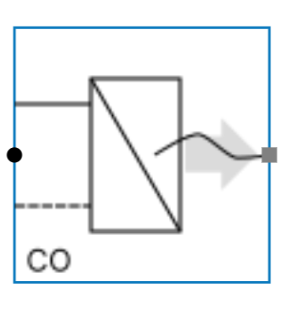
To allow the end‑unit to modulate towards the requested load, Hysopt provides an extra control output connection on the end‑unit. This connection feeds back the actual delivered power:
-
Positive W → heating
-
Negative W → cooling
This feedback is essential because the unit must continuously compare:
Requested load (external signal) vs. Delivered load (hydraulic reality)
3. Mode selection via hysteresis
Because the unit is reversible but cannot heat and cool simultaneously, a temperature hysteresis block is used to determine which mode is active.
Typical logic:
-
External temperature → heating curve → requested heating power
-
External temperature → cooling curve → requested cooling power
-
Hysteresis ensures only one PI controller is active at a time:
-
Heating PI when load > 0
-
Cooling PI when load < 0
-
Deadband prevents rapid switching
-
4. Rescaling the PI controller
The PI controller receives its measurement in W, not in °C or flow. To make the controller stable and responsive, its proportional band must be rescaled relative to the design power.
Rule of thumb (Hysopt convention):
PB = 6.5 × design power
This ensures:
-
stable modulation
-
correct reaction speed
-
no oscillation between heating/cooling
-
proper matching of delivered vs. requested load
5. Resulting behaviour
With this setup, the end‑unit behaves as follows:
-
External signal defines the desired heating or cooling power
-
Hysteresis selects the correct mode
-
PI controller modulates the valve to achieve the requested power
-
Delivered power is fed back to close the control loop
-
Hydraulic parameters remain identical to the standard changeover unit