
UA - calculation of the changeover coil
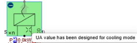
Two separate design conditions exist, but only one end-unit heat exchanger delivers energy (heating or cooling) to the application. For the same design power output, the UA value depends on the application temperature and for the design temperature supply and return condition.
Because HX coils can be sized for only one condition, The designer should set the UA value (heat transfer area × heat transfer coefficient) for the critical condition—either heating or cooling. In Hysopt, the UA value is calculated for that critical condition. After the compute design flows step, the critical application is shown by hovering over the end-unit.
Important:
Hysopt does not recalculate design conditions when heating and cooling UA values differ, which is physically inconsistent. A user can assign any heating and cooling power and design temperature regime to the same end unit; those conditions determine design flow rates and thus affect pipe and pump sizing. The software may gain the option to overwrite design power and conditions in the future based on the critical UA value. During simulation, and for transient effects, the critical UA value is taken into account.
|
Application |
design load |
Design supply temperature |
Design temperature difference |
Application temperature |
LMTD |
UA |
|---|---|---|---|---|---|---|
|
Heating |
10 kW |
40°C |
3°C |
20°C |
18.46 |
0.5417 kW/K |
|
Cooling |
5 kW |
15°C |
4°C |
24°C |
6.805 |
0.7348 kW/K |
Some HVAC engineers size the coil to the minimum UA value, accepting that the design power for the other condition will not be achieved. They do this when one operational mode is less important and they avoid increasing UA (which raises heat exchanger cost) for that condition.
Design flow rate calculation of the changeover coil
We design the flow rate and required pump head using the principle of maximum flow. This choice affects pipe selection, valve selection and the pump head. Because there are two operating conditions—heating and cooling—with separate temperature regimes, we calculate flow rates for both.
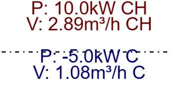
In this application, the heating flow rate determines the changeover pipe size. IN practice, this maximal flow is often used to select pressure independent control valves that have 2 maximal flow rate settings. 1 for heating and 1 for cooling.
Example:
Since the same pump and equipment will likely be used for the same mode, designers should keep design flow rates as close as possible. This affects the return temperature if we imply that the design heating and cooling powers are fixed. If supply temperature is fixed for a given design, reduce the cooling-mode design ΔT to 1.5°C. This has implications on the new critical UA value.
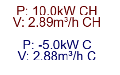
It could be the case that the UA value has been sized for cooling/heating and the PICV has been sized for heating/cooling (max.flow rate). Physically, the design return temperature of the non critical UA-value condition should have been changed to the value that corresponds with the critical UA value.
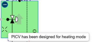
Pump selection of the changeover coil:
Since the same coil serves both heating and cooling, the larger flow determines the required pump head in this mode (see KV formula and the quadratic relation between flow rate and pressure drop). For a single coil, the pump is sized for the largest flow rate. Some applications may differ.
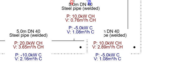
For each pipe segment, the maximum flow will be either heating or cooling mode. The maximum flow in each segment determines the design pressure loss for that segment.
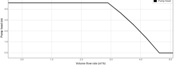
Opening the pump curve lets users verify the flow rate and pump head for which the pump will be sized. In the example below it is 2.89 m³/h and 4.6 m.
Practical example of changeover calculations for UA design optimisation
For the following conditions, UA_cooling is the critical value.
|
Application |
design load |
Design supply temperature |
Design temperature difference |
Application temperature |
LMTD |
UA |
|---|---|---|---|---|---|---|
|
Heating |
10 kW |
40°C |
3°C |
20°C |
18.46 |
0.5417 kW/K |
|
Cooling |
5 kW |
15°C |
4°C |
24°C |
6.805 |
0.7348 kW/K |
Assuming UA equals the critical cooling UA, the actual return temperature in heating mode is:
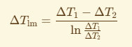
LMTD_new = 10 kW / UA_crit = 13.46 °C
The recalculated return temperature is 28.5 °C.
The recalculated design flow in heating is 0.74 m³/h. Since the design cooling flow is 1.08 m³/h and design flows differ, continue the iteration by selecting a new cooling return temperature to match the recalculated heat flow and recompute the required UA value.
Extra: the design supply temperature can be varied with a solver by ±X°C to find an optimal UA based on KPIs such as:
-
Minimal CAPEX installation
-
…