
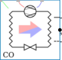
This air-cooled heat pump can deliver either heating or cooling, non simultaneously. The heat pump has 3 control input signals and 1 supply and return changeover pipe connection:
Control inputs:
-
Source Temperature (°C)
-
Heating activation and modulation (0-1)
-
Cooling activation and modulation(0-1)
The different parameters are listed below.
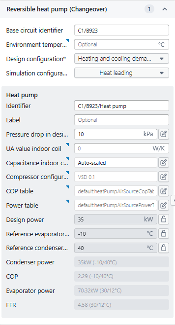
General Configuration
|
Parameter |
Description |
|---|---|
|
Base circuit identifier |
Unique ID linking the heat pump to its hydraulic circuit. It ensures the component connects correctly within the system schematic. |
|
Environment temperature |
Optional external air temperature input for air-source heat pumps. The thermal losses of the system side coil are subjected to this temperature if UA value is specified |
|
Design configuration |
Defines the design mode — typically Heating/ cooling or the maximum demand for reversible systems. It tells Hysopt to size the system for both modes. |
|
Simulation configuration |
Determines which mode leads the simulation (e.g., Heat leading means heating mode governs the control logic). If both heating and cooling request active the HP will choose the sleected mode. |
Heat Pump Parameters
|
Parameter |
Description |
|---|---|
|
Identifier |
Internal name for the heat pump component, automatically derived from the circuit ID. |
|
Label |
Optional descriptive name for easier identification in reports or diagrams. |
|
Pressure drop in design |
Hydraulic resistance across the heat pump at design flow, used for pump sizing and circuit balancing. |
|
UA value indoor coil |
Overall heat transfer coefficient (U·A) of the indoor coil. If set to 0, Hysopt does not consider additional system side coil losses to the environment |
|
Capacitance indoor coil |
Thermal mass of the coil, influencing transient behavior. “Auto-scaled” means Hysopt estimates it based on power and fluid volume. |
|
Compressor configuration |
Defines compressor control type — e.g., VSD 0.1 indicates a variable-speed drive with minimum speed ratio 0.1. |
|
COP table |
Reference table for coefficient of performance (COP) versus operating conditions (evaporator/condenser temperatures). EER is related through the formula EER = COP-1 |
|
Power table |
Reference table for heat pump output power versus operating conditions. |
|
Design power |
Nominal heating/cooling capacity at design conditions. |
|
Reference evaporator temperature |
Temperature at which the evaporator side performance is referenced (e.g., -10 °C for air-source heating). |
|
Reference condenser temperature |
Temperature at which the condenser side performance is referenced (e.g., 40 °C for heating mode). |
Performance Outputs
|
Parameter |
Description |
|---|---|
|
Condenser power |
Calculated heat output at reference conditions. |
|
COP |
Coefficient of Performance — ratio of heat output to electrical input at given conditions. |
|
Evaporator power |
Cooling capacity or absorbed heat at specified evaporator/condenser temperatures. |
|
EER |
Energy Efficiency Ratio — cooling-mode equivalent of COP, defined at cooling reference conditions. |