
Introduction
The Building Simulation Quickstart is a wizard that allows you to quickly generate a simulation-ready Hysopt model for easily processing building simulation results into Hysopt. It is intended to be used at the beginning of a Hysopt project when the goal is to set up the secondary side efficiently and begin analysing system behaviour early. Nonetheless, it can be used at any project stage.
The building simulation quickstart makes it easy to get started with Hysopt simulations and process your building simulation data in Hysopt by automatically generating operational Hysopt models for you. This way, you can focus on system analysis and system optimisation instead.
How to use it
Open the wizard
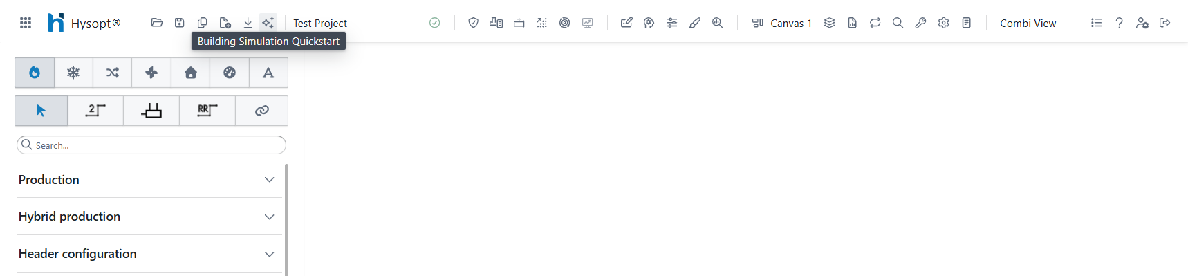
The wizard can be opened at any moment via the building simulation quickstart button ![]()
Wizard Anatomy
The wizard is organised into a small number of clearly separated sections, as shown in the figure below.
-
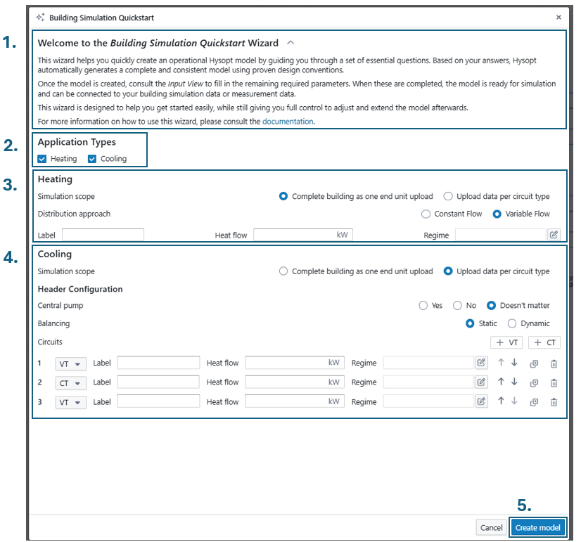
Welcome section that briefly explains the purpose and possibilites of the wizard.
-
Application types
Here you choose which secondary-side application(s) you want to generate. Heating and cooling can be enabled independently. Based on this selection, the corresponding configuration panels appear below. -
Heating configuration
This section appears when heating is enabled as application type, meaning that a heating system will be part of the generated Hysopt model. Depending on the simulation scope, the heating header can be configured as “one unit for a complete building” or as a header with “end units per circuit type”. The exact parametrisation of each simulation scope option is elaborated below. -
Cooling configuration
This section appears when cooling is enabled, meaning that a cooling system will be part of the generated Hysopt model. Depending on the simulation scope, the cooling header can be configured as “one unit for a complete building” or as a header with “end units per circuit type”. The exact parametrisation of each simulation scope option is elaborated below.
-
Model generation
Use Create model to generate the model on the canvas. Cancel closes the wizard without generating anything.
Simulation scope: Full building as one end unit option
Select “Complete building as one end unit upload” as simulation scope when a high-level representation of the secondary side is sufficient. This option is typically used for feasibility work or early concept design, where internal distribution details are intentionally abstracted.
With this scope, the wizard generates a compact model with a single equivalent end unit representing the full building. You can parametrise this single equivalent end unit from within the wizard by filling in the following parameters
-
Label: Optional name used for the generated end unit/circuit. (can also be provided later)
-
Heat flow: optional value to represent the buildings design heat flow (can also be provided later)
-
Regime: optional field to enter the buildings design temperature regime regime selection (can also be provided later)
The parametrisation of “Label”, “Heat Flow” and “Regime” are fully optional in the wizard. You can proceed to the model generation without filling in the parameters.
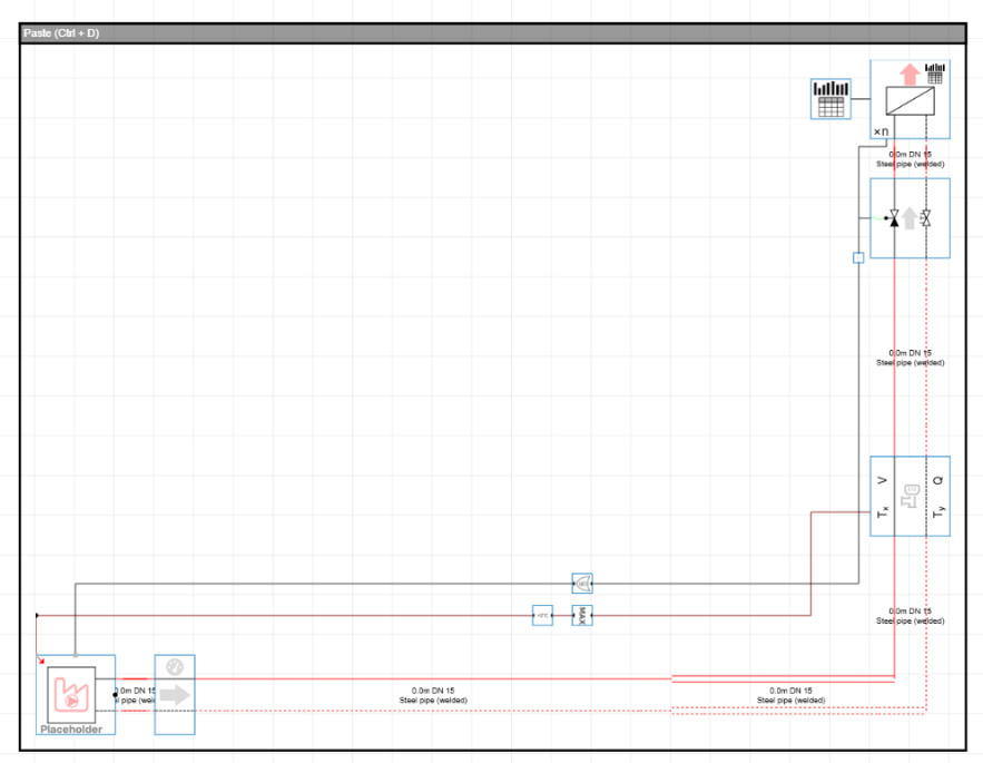
The result will be a single equivalent end unit that can be linked to your building simulation data easily as depicted in the figure below. No header or branch structure is created, so the model remains intentionally compact and focused on an aggregated building representation.
The generated model is created as in a paste box that you can freely place in your Hysopt model by using Ctrl+D, or clicking the paste bar at the top of the box.
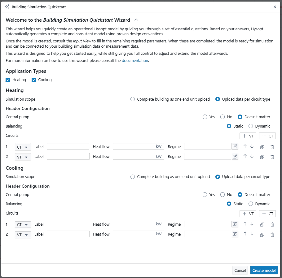
Simulation scope: Upload data per circuit type (Header configuration)
Select the upload data per circuit type option when the distribution structure should be represented explicitly, for example when multiple subsystems must be modelled separately or when branch-level design choices are already known and preferred to be taken into account in the simulation.
When this option is active, the wizard exposes a more detailed header configurator.
Header configurator
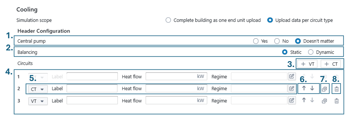
The header configurator allows you to build custom headers with the building simulation quickstart. The anatomy of the header configurator section is explained in more detail below:
-
Central pump
Select whether the generated header should include a central distribution pump.-
Yes: a central pump is included in the generated header.
-
No: no central pump is generated.
-
Doesn’t matter: the model is generated without forcing this choice, which is useful when the distribution concept is not fixed yet.
-
-
Balancing
Select the intended balancing concept for the generated distribution.-
Static: intended for statically balanced distribution concepts.
-
Dynamic: intended for dynamically balanced distribution concepts using PICVs
-
-
Add circuits
Use the +VT and +CT buttons to add circuits (branches) to the header.-
VT (Variable Temperature): for branches where the supply temperature can be controlled to a variable temperature using a mixing circuit.
-
CT (Constant Temperature): for branches operating at a fixed supply temperature level.
-
-
Circuits overview
The circuit list shows all configured circuits. Each row corresponds to one branch that will be generated on the header. The branches will be created in the order as shown in the circuit overview. -
Circuit parametrisation
-
Type selector: defines if the circuit is a VT- or CT-circuit.
-
Label: name used at the branch after generation
-
Heat flow: optional value to represent the buildings design heat flow (can also be provided later)
-
Regime: optional field to enter the buildings design temperature regime regime selection (can also be provided later)
The fields Label, Heat flow, and Regime are optional in the wizard, so you can generate the model without filling them in.
However, it is recommended to provide as much of this information as possible. Doing so allows Hysopt to prefill parameters during the model generation, set up the intended control setpoints where applicable, and apply any required corrections to the branch configuration.
-
Reorder circuits
Use the up/down arrows to change the order of circuits on the header. The displayed order in the circuits overview will also be the order of the branches in the generated header (1 is most leftward branch with subsequent branches added on the right-hand side -
Clone circuit
Duplicate a circuit row to reuse an existing configuration. Useful when several branches share similar settings and speeding up the workflow. -
Remove circuit
Delete a circuit from the configuration.
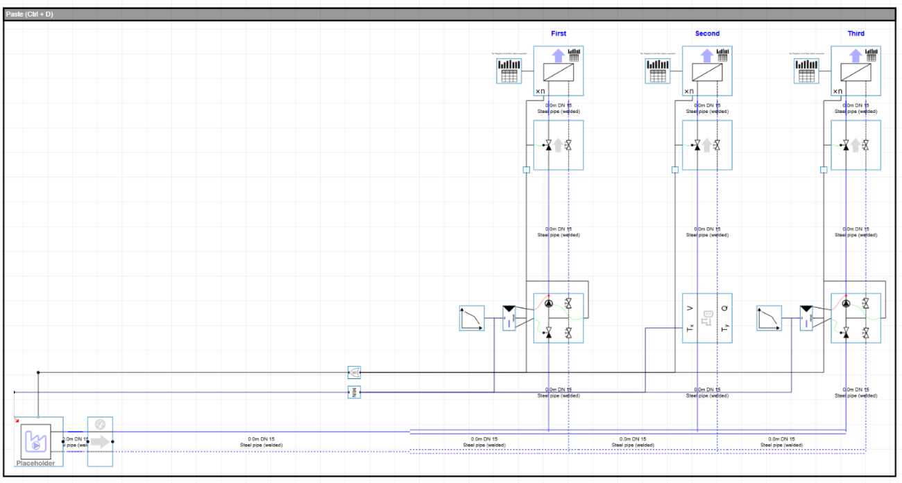
As a result, the wizard generates a header containing the selected circuits. For each circuit, an equivalent end unit is created, allowing building simulation data to be linked per circuit. Any remaining detailed inputs can then be completed after generation through the Input view.
The generated model is created as in a paste box that you can freely place in your Hysopt model by using Ctrl+D, or clicking the paste bar at the top of the box.
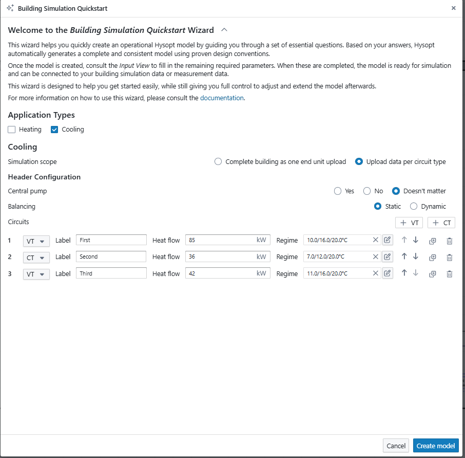
Example of Upload data per circuit type
From model generation towards simulation
Model generation
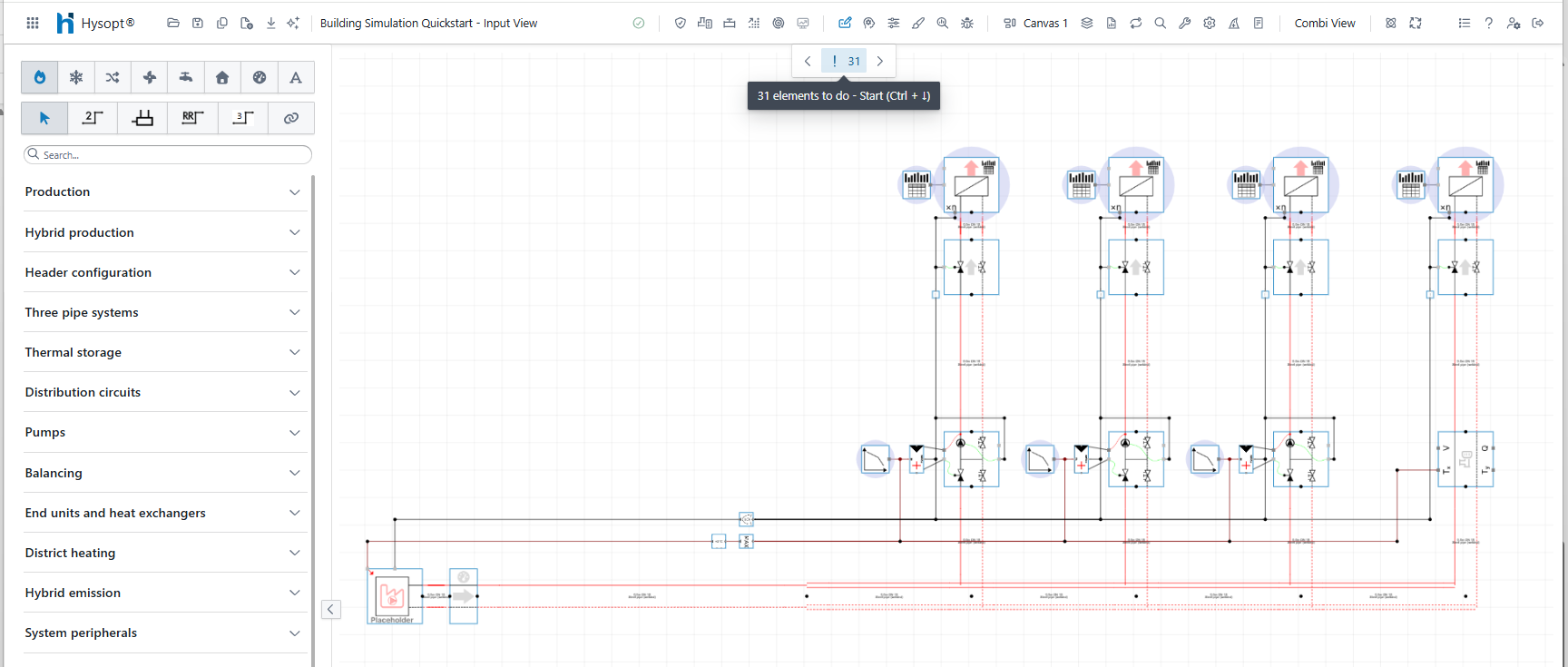
After pasting the generated model on the canvas with Ctrl+D, the canvas contains the requested topology of the secondary side. The new secondary side is automatically connected to an energy centre placeholder at the primary side of the system. The energy centre placeholder is an ideal production unit that is added automatically to allow for early simulations without defining a detailed production concept, or to be easily replaced with an actual energy centre template. more information on the energy centre placeholder can be found at energy centre placeholders.
In any case, the system is not ready yet for simulation after the model generation as we still need to fill in the remaining input parameters that could not be derived from the building simulation quickstart inputs. To easily fill the remaining input parameters, you can consult the input view.
After model generation, the system is not ready yet for simulation. The remaining inputs still need to be configured, for which you can consult the Hysopt input view.
Completing inputs using the Input view
The Input view provides a structured way to complete the generated model. It guides you to the remaining parameters that must be configured before simulation. Typical items include branch design temperatures, uploaded custom building data files for the end units, and regime settings such as heating or cooling curves for variable temperature circuits.
Automatic control propagation
Once the required inputs are configured, the model is ready for simulation with the energy centre placeholder. The generated wiring is designed in such a way that the secondary side drives the activation and setpoins of the production side without manual setup. The setpoint and activation signals of each branch are automatically propagated through the primary side over a “bus” concept up till the energy centre placeholder.
Hysopt models that are generated with the building simulation quickstart use following conventions to easily understand the purpose of each control wire:
-
Black: Activation signal
-
Dark-red: Setpoint temperature for heating
-
Dark-blue: Setpoint temperature for cooling
Energy centre placeholder and next steps
The energy centre placeholder included by the wizard acts as an ideal source to support early simulation. In later stages, the placeholder can be replaced with an actual production concept using template replacement concept, allowing the project to transition into the energy centre optioneering phase.
Modular design
Main headers and subheaders
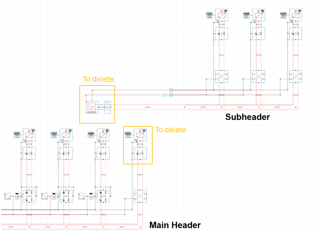
The building simulation quickstart wizard can also be used to build up a complete system with main headers and subheaders in a modular way. The wizard can be used multiple times within the same project to build a hierarchical structure. A common approach is to create a main header first and then generate a subheader for a specific branch.
In order to replace an equivalent end unit with a subheader, only the end unit module should be deleted at the main header. Next, the subheader can be created and connected at the location where you have deleted the end unit. In general, the pipe and the activation signal (black control line) of the subheader must be connected to the main header’s branch. The procedure is displayed in the example below:
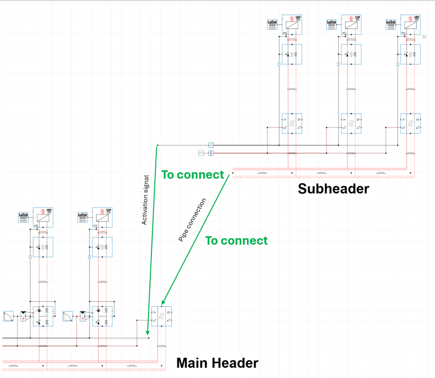
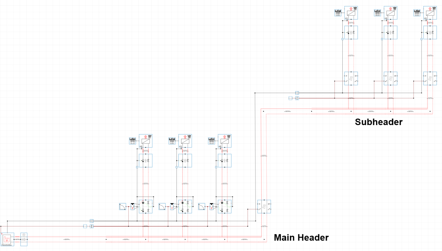
When combining headers, the activation signal connection and the hydraulic connection always need to be connected manually from the subheader to the main header. In most cases, it is not necessary to manually connect the setpoint control lines (dark-blue/dark-red control lines).
The setpoint at the main header can typically be derived from the design setpoint of the main header’s CT-circuit, or from the heating curve from the main header’s VT-circuit. If you want to deviate from that approach, you can always propagate the setpoint signal from the subheader to the main header. You can do so by opening up the dark-red/dark-blue connection at the corresponding branch at the main header and connect the bus - setpoint signal from the subheader to this new, open connection.
Conclusion
The Building Simulation Quickstart Wizard offers a structured starting point for secondary-side modelling in Hysopt. It supports both a compact representation of the full building as a single end unit and a more detailed representation using a header with multiple branches. By generating standard circuits and preparing the main control connections automatically, it strongly reduces the setup time of an operational Hysopt model and enables simulation once the remaining inputs are completed.
For larger projects, the wizard can be reused to assemble multi-level header systems using a modular design appraoch.